
Header for implantable medical for use with both unipolar and bipolar leads

a medical device and header technology, applied in electrotherapy, therapy, etc., can solve the problems of increasing inventory cost and unit scraping

Active Publication Date: 2007-02-06
CARDIAC PACEMAKERS INC
View PDF5 Cites 10 Cited by
  • Summary
  • Abstract
  • Description
  • Claims
  • Application Information

AI Technical Summary

Benefits of technology

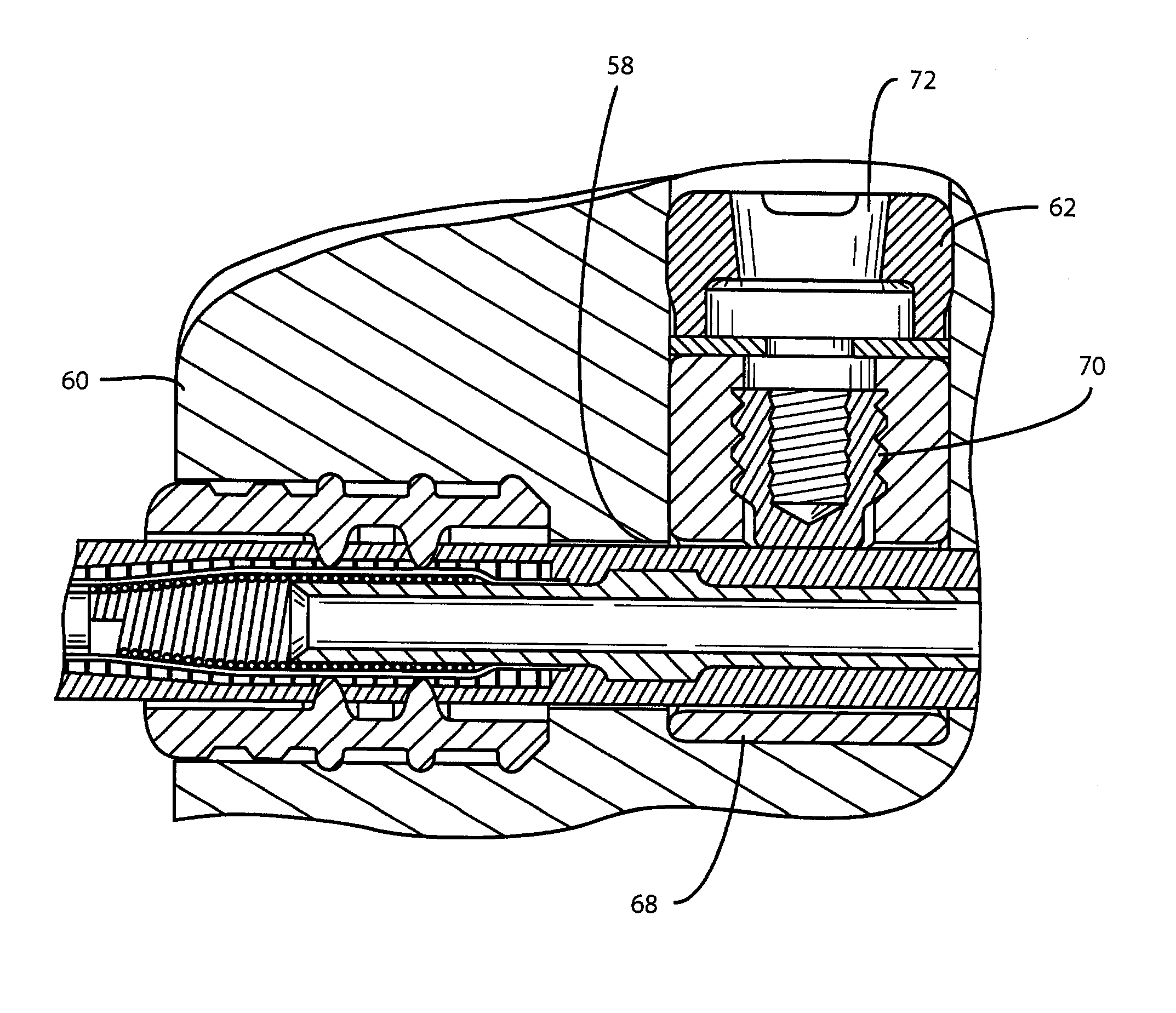
[0010]In accordance with the present invention, there is provided a header for an implantable medical device where the header has contacts in a lead terminal receiving bore, the contacts being adapted to mate with a proximal terminal of either a unipolar or a bipolar lead. The proximal terminal of the unipolar lead has a proximal pin contact adjacent to a plastic insulating sleeve. The proximal terminal of the bipolar lead has a proximal pin contact and a distal ring contact. The header comprises a plastic body member that is adapted to be affixed to a housing of an implantable medical device. A longitudinal, lead terminal receiving bore is formed in the plastic body member as are first and second longitudinally spaced apertures that extend transversely to and intersect with the bore formed in the body member. First and second conductive connector blocks are respectively placed in the first and second apertures. Each of the connector blocks has a bore concentric with the bore formed in the plastic body member and a threaded bore that extends transverse to and intersects with the bore of the connector block. The bore of the second connector block has a diameter large enough to receive the pin contact of either a unipolar lead or a bipolar lead and the bore of the first connector block has a diameter large enough to receive the distal ring contact of a bipolar lead or the insulating sleeve of a unipolar lead therein. A first set screw is inserted into the threaded bore in the second connector block and is adapted to lock the pin contact of either a bipolar lead or a unipolar lead in the second connector block. Similarly, a second set screw is inserted into the threaded bore in the first connector block and is adapted to engage either the ring contact of a bipolar lead or the insulating sleeve of a unipolar lead. The threads in the threaded bore of the first connector block are such as to preclude the second set screw from damaging the insulating sleeve of the unipolar lead when the second set screw is fully advanced into the threaded bore in the first connector block.

Problems solved by technology

This necessarily increases the cost of inventory, and when it is considered that such devices have a limited shelf life, it will frequently happen that units will have to be scraped because of a lack of demand for particular models.

Method used


Image

  • Header for implantable medical for use with both unipolar and bipolar leads
  • Header for implantable medical for use with both unipolar and bipolar leads
  • Header for implantable medical for use with both unipolar and bipolar leads

Examples


Embodiment Construction

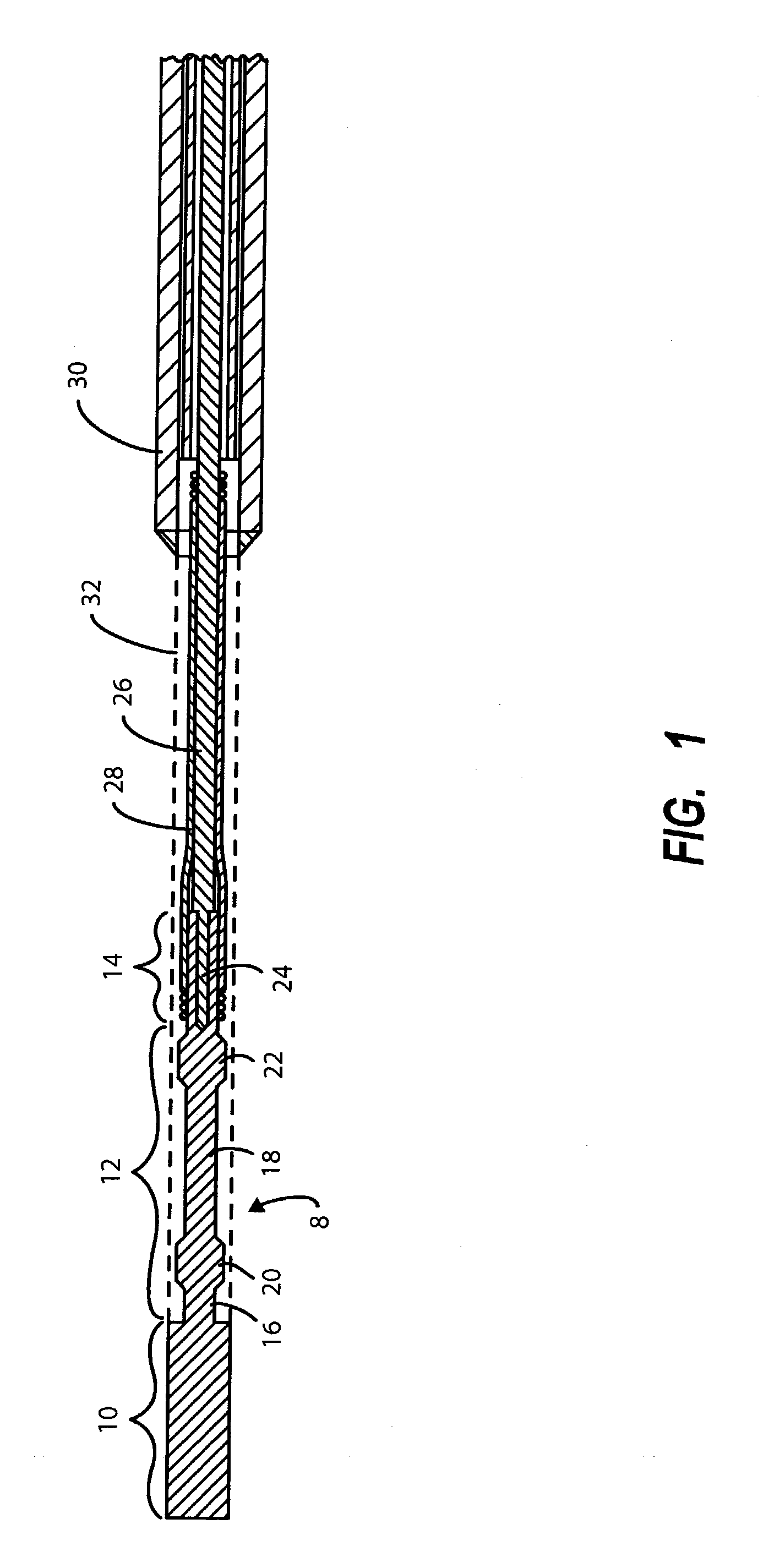
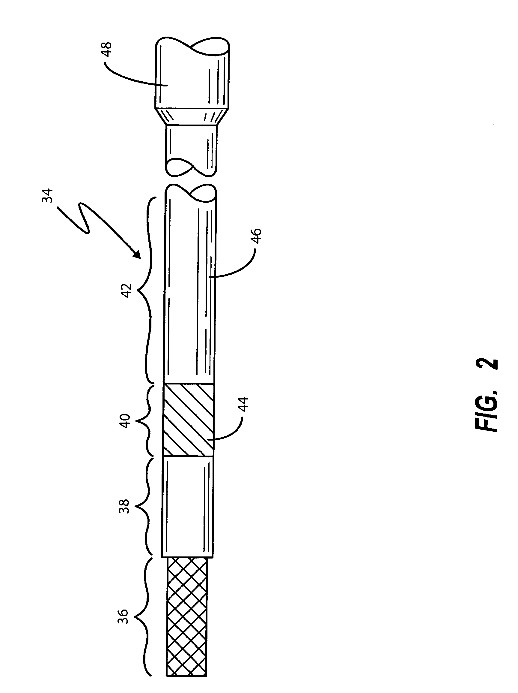
[0017]Referring to FIG. 1, there is shown a greatly enlarged side elevational view of the proximal terminal portion of a unipolar lead. While the present invention does not pertain to the construction of leads per se, a description of a unipolar lead terminal (FIG. 1) and a bipolar lead terminal (FIG. 2) deemed helpful in understanding the problem solved by the present invention.

[0018]Referring to FIG. 1, the unipolar lead includes a conductive metal terminal pin indicated generally by numeral 8 that can be considered as being partitioned into three contiguous zones 10, 12 and 14. In zone 10, the terminal pin 8 is generally cylindrical of a uniform diameter. In zone 12, the pin has reduced diameter portions 16 and 18 that define anchor segments 20 and 22. In zone 14, the pin is tubular and a bore 24 is formed longitudinally therein.

[0019]Crimped or otherwise affixed within the lumen of the tubular segment 24 is a core wire 26 that extends the length of the lead and connects to an el...


PUM


Abstract

The present invention provides a header for an implantable medical device that allows it to be used with either a unipolar lead or a bipolar lead. The set screw normally engaging a ring contact on a bipolar lead is stopped from extending far enough into an insulating layer on a unipolar lead to cause damage to the insulating layer. The use of the universal header of the present invention works to significantly reduce the number of different models of implantable medical devices that a manufacturer must have available.

Description

BACKGROUND OF THE INVENTION[0001]I. Field of the Invention[0002]This invention relates generally to the mechanical design of a header for an implantable medical device, such as a cardiac pacemaker or cardiac pacemaker / defibrillator, and more particularly to the design of a header having a lead receiving bore with contacts for mating with either a unipolar lead or a bipolar lead.[0003]II. Discussion of the Prior Art[0004]An implantable medical device typically comprises a metal housing hermetically sealing a battery, a pulse generator circuit and a microprocessor-based controller for the pulse generator such that cardiac stimulating pulses are generated on a timed basis determined by the microprocessor-based controller. Affixed to an exterior wall of the housing is a header for operatively coupling the contacts on the proximal terminals of one or more medical leads to feed-through pins that enter the housing through seals where they connect to circuit inputs and outputs.[0005]The med...

Claims


Application Information

Patent Timeline
IPC IPC(8): A61N1/375
CPCA61N1/3752
Inventor SPADGENSKE, SCOTT A.
Owner CARDIAC PACEMAKERS INC
Learn More