Wing driving apparatus

a technology for driving apparatuses and wing bodies, applied in the direction of servomotors, fluid couplings, servomotor parallel arrangements, etc., can solve the problem of temporarily uncontrollable flight of airplanes, and achieve the effect of improving the safety of airplanes in fligh

Active Publication Date: 2007-02-13
TEIJIN SEIKI CO LTD
View PDF7 Cites 22 Cited by
  • Summary
  • Abstract
  • Description
  • Claims
  • Application Information

AI Technical Summary

Benefits of technology

[0014]Accordingly, an object of the present invention is to provide a wing driving apparatus which is capable of improving safety of an airplane in flight.
[0016]As described above, the wing driving apparatus of the invention can change over the actuator for driving the wing from one actuator to another actuator through operation of the follower signal generator part of only the first controller unit, not through operations of both the first controller unit and the second controller unit. This feature ensures smoothly switching over of the actuator for driving the wing. Accordingly, improved safety of the airplane in flight is secured.
[0018]With such an arrangement, the wing driving apparatus of the invention can detect, in advance, as to whether or not the second controller unit is able to operate the second actuator to drive the wing. Accordingly, the wing driving apparatus can improve safety of the airplane in flight when comparing with the wing driving apparatus not having the detector part.

Problems solved by technology

As a result, the flight of the airplane is temporarily uncontrollable, though infrequently.

Method used


Image

  • Wing driving apparatus
  • Wing driving apparatus
  • Wing driving apparatus

Examples


Embodiment Construction

[0025]The preferred embodiments of the invention will be described with reference to the accompanying drawings.

[0026]A system configuration of a wing driving apparatus which is an embodiment of the present invention will be described.

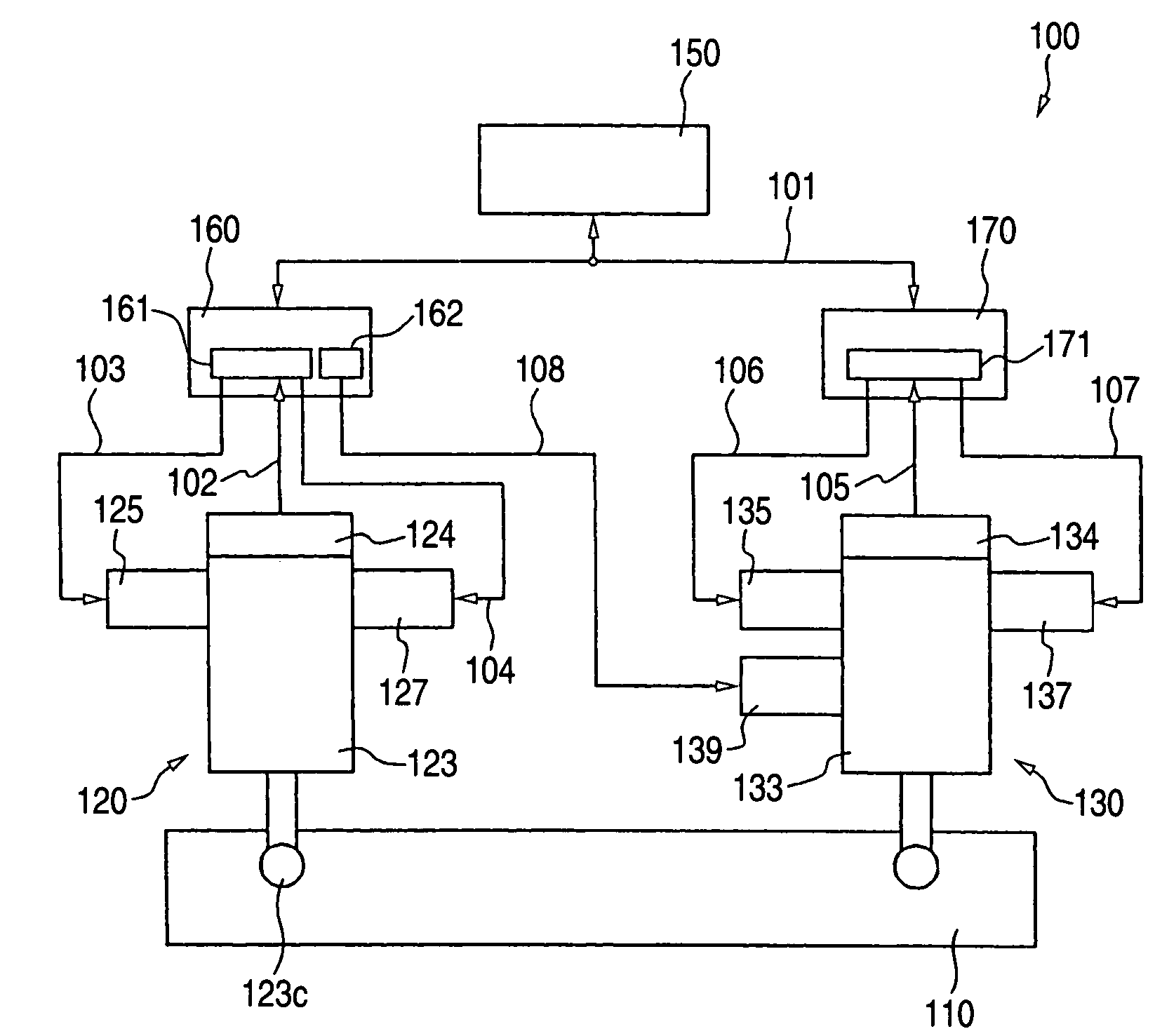
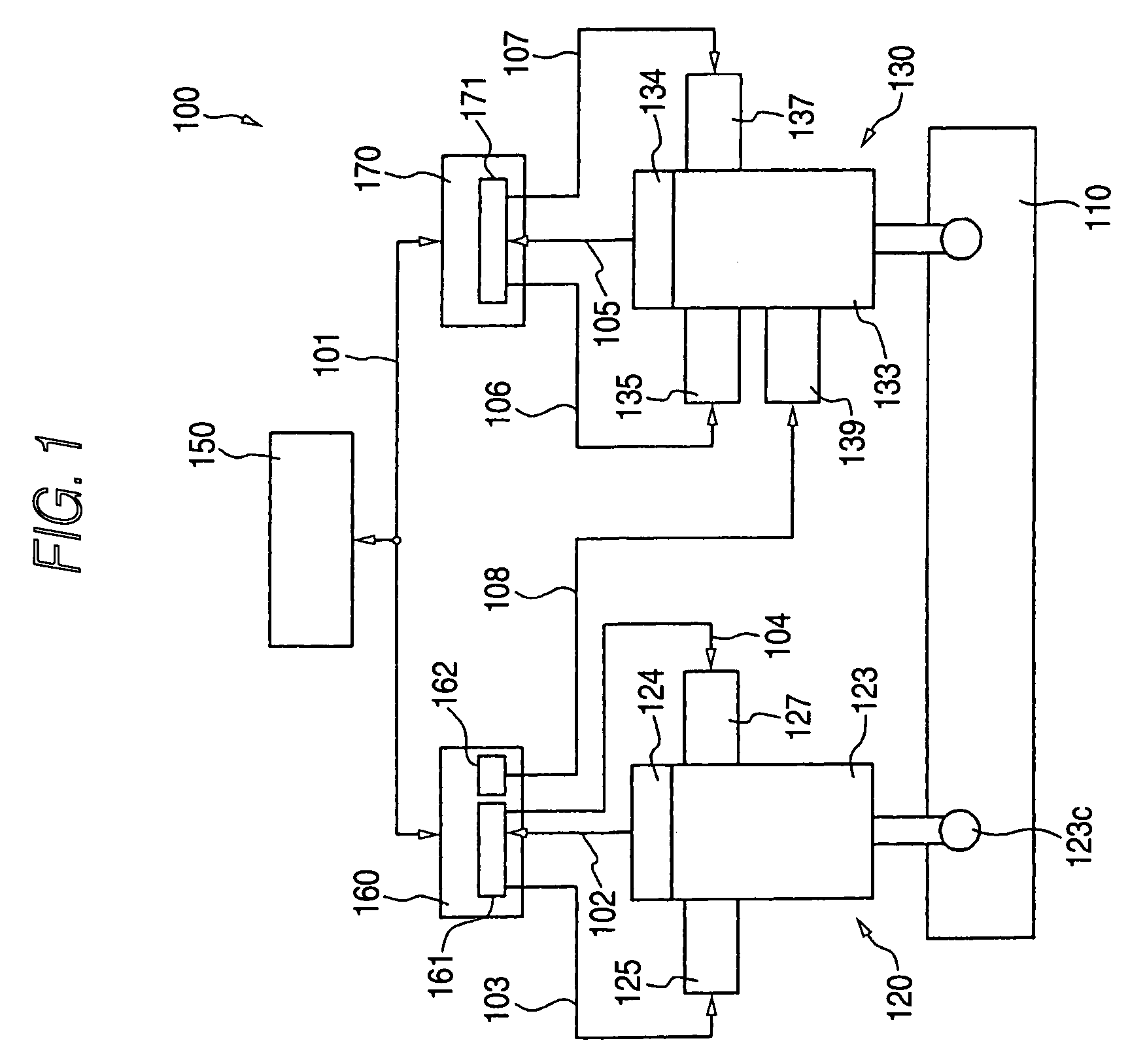
[0027]As shown in FIG. 1, a wing driving apparatus 100 which is an embodiment of the present invention is comprised of a steering wing 110, a servo actuator 120 as a main actuator for driving the steering 110, a servo actuator 130 as a sub-actuator for driving the steering wing 110, and a flight controller 150 as a drive signal generator part for generating a drive signal which operates the servo actuator 120 and the servo actuator 130 to drive the steering wing 110.

[0028]The wing driving apparatus 100 includes a controller 160 as a main controller unit which receives a drive signal from the flight controller 150 via an electric wire 101. The controller 160 includes a drive circuit 161 as a main drive controller part and a follower signal generator circ...


PUM


Abstract

A wing driving apparatus is made up of a flight controller part for generating a drive signal, first and second servo actuators, a first controller unit having a first drive circuit, and a second controller unit having a second drive circuit. The first controller unit includes a follower signal generator circuit for generating a follower signal. The second servo actuator includes a solenoid valve for invalidating a control to the second serve actuator based on the drive signal from the second drive circuit in response to the follower signal, whereby the second second servo actuator follows the steering wing when the first drive circuit is able to operate the first servo actuator to drive the steering wing.

Description

[0001]The present application is based on Japanese Patent Application No. 2002-343777, the entire contents of which are incorporated herein by reference.BACKGROUND OF THE INVENTION[0002]1. Field of the Invention[0003]The present invention relates to a wing driving apparatus for driving a wing of an airplane.[0004]2. Related Art[0005]There is known a wing driving apparatus for driving the wing in which the wing is driven by all of plural actuators (see JP-A-S64-41498 pp 4 to 7, FIG. 2, for example).[0006]Another wing driving apparatus 900 as shown in FIG. 6 is also known. In the wing driving apparatus, the wing is driven by using some of plural actuators. If any of those actuators malfunctions, the wing is uninterruptedly driven by using an actuator having not been used for driving the wing, instead of the malfunctioning one.[0007]The wing driving apparatus 900 is made up of a steering wing 910, servo actuators 920 and 930 for driving the steering wing 910, a flight controller 950 fo...

Claims


Application Information

Patent Timeline
Patent Type & Authority Patents(United States)
IPC IPC(8): B64C13/12B64C13/42F15B18/00
CPCF15B18/00B64C13/42B64C13/505
Inventor TANAKA, TERUAKIKAMIMURA, TOSHIO
Owner TEIJIN SEIKI CO LTD
Why Eureka
Try Eureka