
Wheel bracket mechanism for an electric wheelchair equipped with auxiliary wheels

a technology of auxiliary wheels and brackets, which is applied in the direction of electric propulsion mounting, wheelchair/patient conveyance, transportation and packaging, etc. it can solve the problems of unstable electric wheelchairs, unfit elderly and handicapped people, and vertical vibrations of rectangular frames, etc., and achieve the effect of stable wheelchairs

Inactive Publication Date: 2007-02-13
PIHSIANG MACHINERY MFG
View PDF4 Cites 82 Cited by
  • Summary
  • Abstract
  • Description
  • Claims
  • Application Information

AI Technical Summary

Benefits of technology

The mechanism enhances stability and safety by smoothing the expansion and compression of the pedestal assemblies, reducing elastic shakes and preventing the wheelchair from tilting, ensuring a comfortable and secure ride on various slopes.

Problems solved by technology

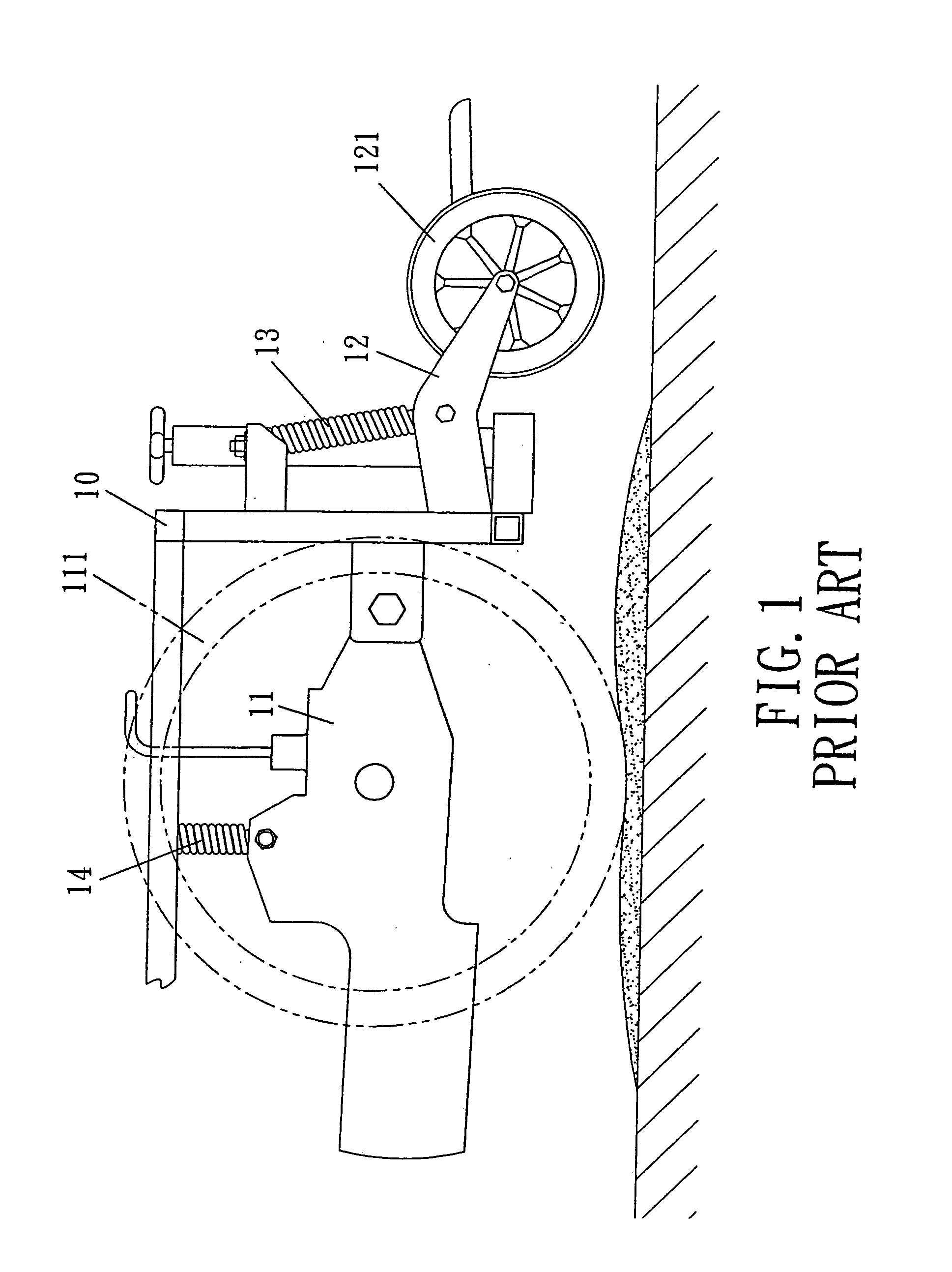
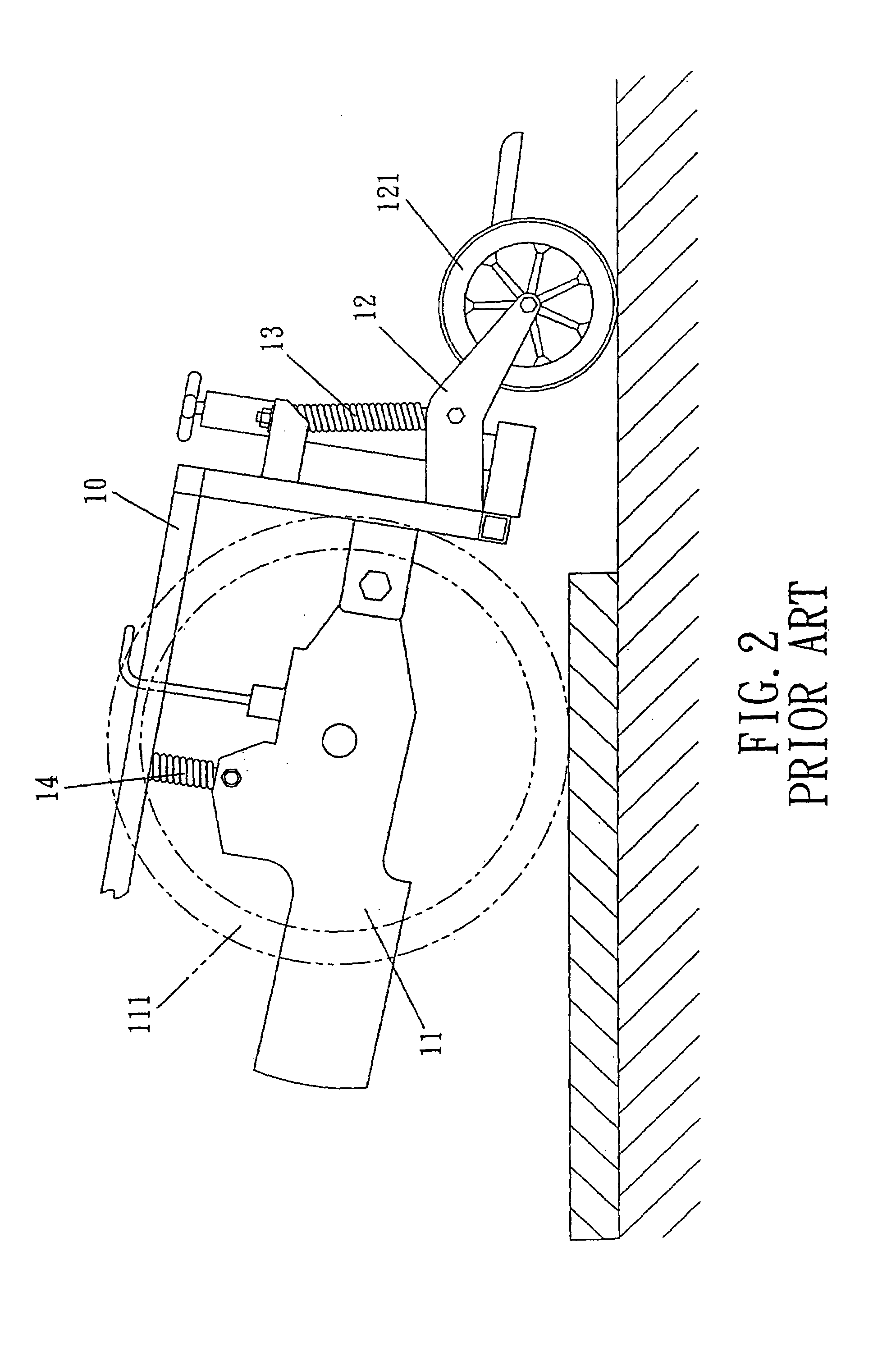
First, in terms of stability, the conventional rectangular frame 10 just takes advantage of the longitudinal expansion and compression of the compressive spring 14 to maintain the stability. Although the elastic forces of the compressive spring can force the front wheel bracket 11 and the drive wheel bracket 13 to move back to the predetermined position, it may also cause vertical vibrations of the rectangular frame 10. Such an unstable electric wheelchair is not able to provide a comfortable driving to the occupants, especially to the old patients, most of them are old and disabled.
Second, in terms of security, although the conventional rectangular frame 10 is allowed to expand or contract with the help of the compressive spring 14. However, the contraction or expansion of the front wheel bracket 11 and the drive wheel bracket 13 are performed independently and individually due to no coordinating device disposed therebetween, furthermore the rear wheel bracket 12 is incompressible, Thereby the conventional rectangular frame 10 will be tilted and swayed along with the motion of the respective wheel brackets, and the center of gravity of the wheelchair moves back and forth substantially. Such that the wheelchair is susceptible to tip, it is absolutely unfit for the old and handicapped people.

Method used


Image

  • Wheel bracket mechanism for an electric wheelchair equipped with auxiliary wheels
  • Wheel bracket mechanism for an electric wheelchair equipped with auxiliary wheels
  • Wheel bracket mechanism for an electric wheelchair equipped with auxiliary wheels

Examples


Embodiment Construction

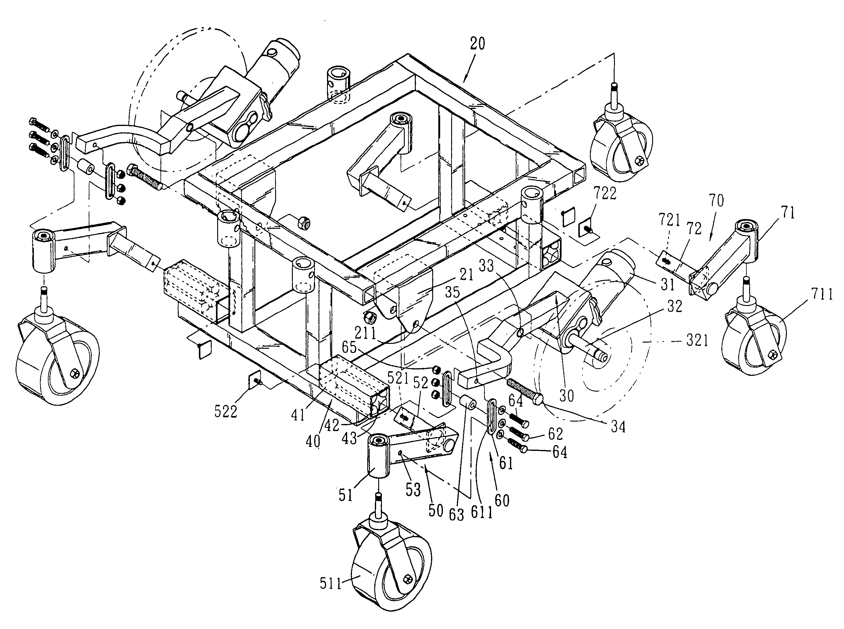
[0018]Referring to FIGS. 2–3, wherein, in accordance with the present invention, a wheel bracket mechanism for an electric wheelchair equipped with auxiliary wheels is shown and generally comprises a frame 20, a pair of drive wheel brackets 30, four pedestal assemblies 40, a pair of castor brackets 50, a pair of oscillating assembly 60 and a pair of anti-tipping brackets 70.

[0019]The frame 20 in shape of rectangle is provided with two ear members 21 at both sides with symmetrical to each other and located between the front and rear end. Each of the ear members has an aperture 211 defined thereof.

[0020]The drive wheel bracket 30 is a crank member, at the rear end of which is secured a motor 31 and drive shaft 32 respectively. The drive shaft 32 serves to drive the drive wheel 321. At the middle of the drive wheel bracket 30 is provided with a hole 33 which corresponding to an aperture 211 of the ear member 21 of the frame 20, and by an axle 34 inserting through the hole 33 and the ap...


PUM


Abstract

A wheel bracket mechanism for an electric wheelchair equipped with auxiliary wheels, which comprises a frame, a pair of drive wheel brackets, four pedestal assemblies, a pair of caster brackets, a pair of oscillating assembly and a pair of anti-tipping brackets. The frame is provide with a pair of castor brackets at the front end and a pair of anti-tipping brackets at the rear end thereof, a pair of drive wheel brackets are secured to the frame with a front end stretching ahead of it and located between the castor brackets and the anti-tipping brackets, and between the castor brackets and the drive wheel bracket disposed an oscillating assemblies, four pedestal assemblies equipped with cushioning blocks are disposed at both sides of the front and rear end of the frame respectively in pairs with located opposite to each other.

Description

BACKGROUND OF THE INVENTION[0001]1. Field of the Invention[0002]The present invention relates a wheel bracket mechanism for an electric wheelchair, and more particularly to a wheel bracket mechanism for an electric wheelchair equipped with auxiliary wheels.[0003]2. Description of the Prior Arts[0004]Electric wheelchairs have become an indispensable means of transport for the ailing old or the handicapped people to help them in indoor and out activities, such as traveling and boarding on the airplane, and so on.[0005]A wheel bracket mechanism of a conventional electric wheelchair (and transport means or the like) is normally rectangular-formed as shown in FIG. 1, which discloses a rectangular frame 10 is provided with front wheel bracket 11 and rear wheel bracket 12 respectively at the front end and the rear end thereof for being mounted with front wheel and rear wheel respectively, and a drive wheel bracket 13 (the drive wheel bracket 13 is mounted with drive wheel) is disposed betw...

Claims


Application Information

Patent Timeline
Patent Type & Authority Patents(United States)
IPC IPC(8): B60G5/04A61G5/04A61G5/06A61G5/10
CPCA61G5/043A61G5/06Y10S180/907A61G2005/1078A61G5/1078
Inventor WU, DANIEL P. H.
Owner PIHSIANG MACHINERY MFG
Learn More