Selectively expandable and releasable stent

a stent and releasable technology, applied in the field of stents, can solve the problems of not being able to adjust the diameter of the stent, not being able to adjust the position of the stent in the vessel, and blood cannot flow therepas

Inactive Publication Date: 2007-02-13
XTENT MEDICAL INC
View PDF4 Cites 338 Cited by
  • Summary
  • Abstract
  • Description
  • Claims
  • Application Information

AI Technical Summary

Benefits of technology

[0006]The present invention seeks to provide further improvements in the WO 99 / 13800 stent. The stent is selectively expandable / contractible throughout a range of cross-sectional areas, and is easily insertable and removable.
[0017]In accordance with a preferred embodiment of the present invention pulling the inner and outer coupler tubes generally proximally releases the tongue from the apertures of the outer elongate member, thereby allowing proximally-directed removal of the inner and outer coupler tubes and the manipulator tube.

Problems solved by technology

A disadvantage of such prior arts is that as long as the balloon is expanded, blood cannot flow therepast.
There is no possibility of adjusting the diameter of the stent.
After having installed the stent, there is no possibility of adjusting the stent position in the vessel.
Another disadvantage is that prior art stents cannot be installed in very constricted vessels without first enlarging the constricted vessel.
This balloon procedure can lead to endothelial ablation.

Method used


Image

  • Selectively expandable and releasable stent
  • Selectively expandable and releasable stent
  • Selectively expandable and releasable stent

Examples


Embodiment Construction

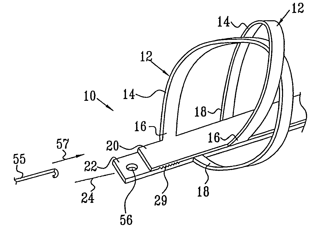
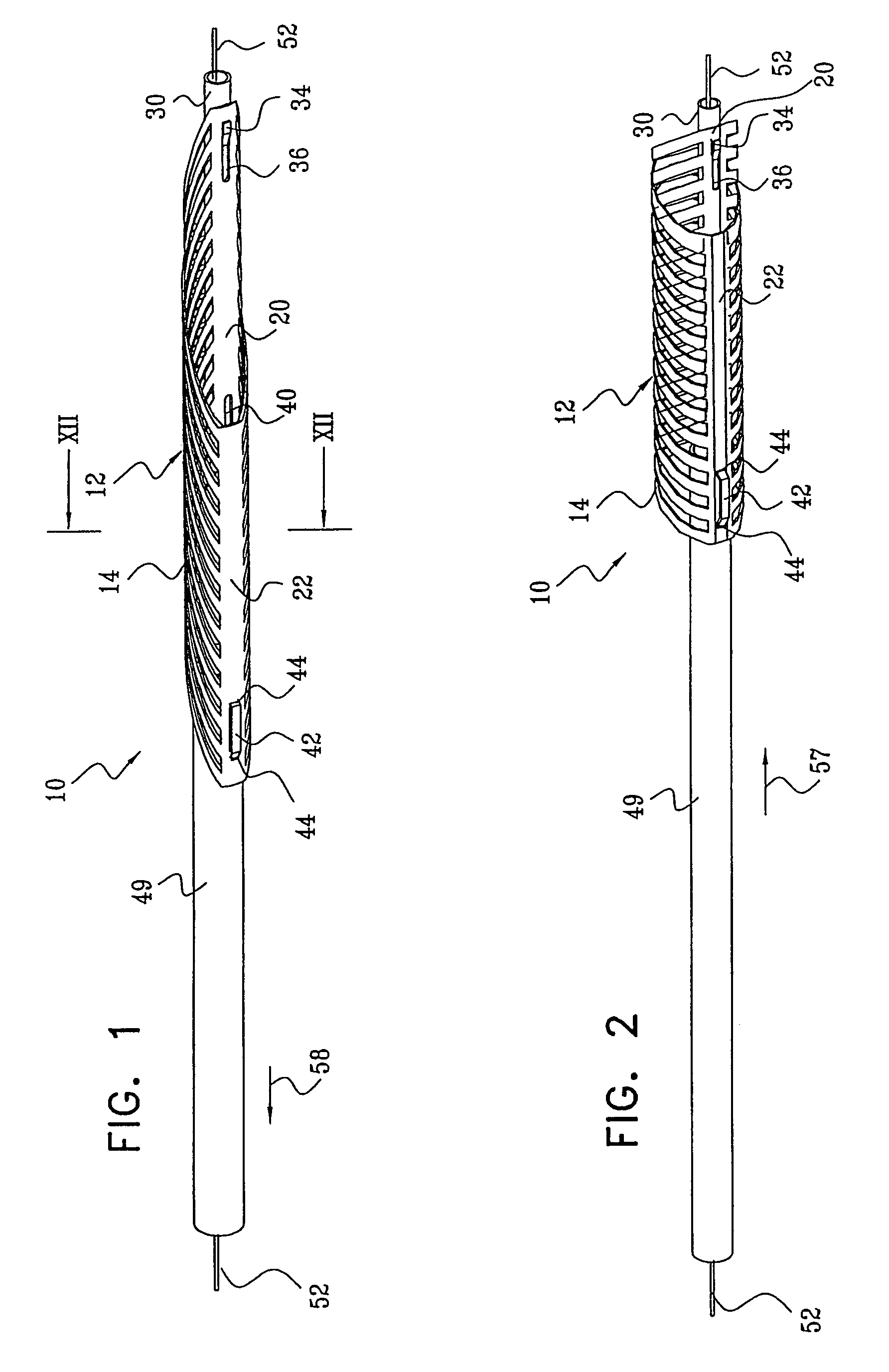
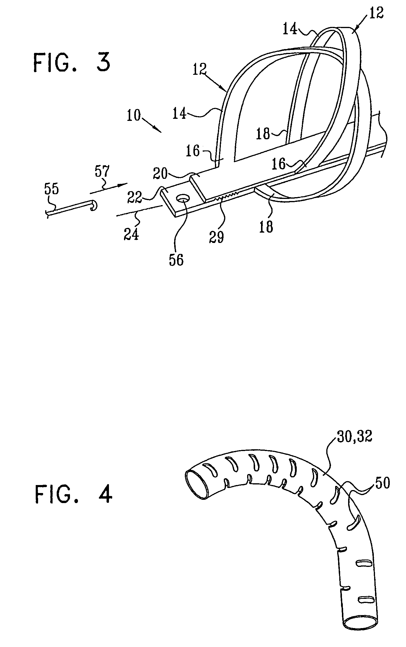
[0031]Reference is now made to FIGS. 1–3 which illustrate a stent 10 constructed and operative in accordance with a preferred embodiment of the present invention.

[0032]Stent 10 includes a plurality of loops 12, each loop 12 constructed of an arcuately formed wire 14 with a first end 16 and a second end 18 (FIG. 3). It is noted that throughout the specification and claims the term wire encompasses any slender element such as wire, rod, bar, cable, or the like, having any cross-sectional shape such as flat, rectangular or round. Wire 14 is typically made of any medically safe material and may be flexible if desired. For example, wire 14 may be made of a resilient material, such as heat-treated nitinol, wherein after inserting stent 10 in a lumen (not shown) and expanding stent 10 to its expanded position (FIG. 2), wires 14 tend to spring outwards against the inner walls of the lumen. This helps to anchor stent 10 in place and prevent migration of stent 10 inside the lumen.

[0033]First ...


PUM


Abstract

A stent including a plurality of loops, each of the loops includes an arcuately formed wire with a first end and a second end, the first end being attached to an inner elongate member and the second end being attached to an outer elongate member, the inner and the outer elongate members being arranged to slide with respect to each other along a common longitudinal axis, wherein sliding of the inner and the outer elongate members with respect to each other changes a cross-sectional area of each of the loops, characterized in that the inner and outer elongate members are attached to inner and outer coupler tubes, and are selectively releasable from the inner and outer coupler tubes, the inner coupler tube being nested inside the outer coupler tube.

Description

FIELD OF THE INVENTION[0001]The present invention relates generally to a stent with a selectively changeable cross-sectional area which is easily inserted into and removed from a body vessel, and which is selectively expandable and releasable.BACKGROUND OF THE INVENTION[0002]Stents are well known tubular support structures inserted into body vessels, ducts, lumens and the like, in various medical procedures. For example, stents may be inserted in strictures in the common bile duct, blood vessels, urethra and other organs. Stents are generally mounted on a delivery catheter which is inserted over a thin guidewire. The catheter is introduced into the particular vessel, and the stent is released from the catheter and fixed in a chosen location in the vessel by expanding a balloon upon which the stent is mounted in a closed position. A disadvantage of such prior arts is that as long as the balloon is expanded, blood cannot flow therepast. Both the balloon and the stent have only two pos...

Claims


Application Information

Patent Timeline
Patent Type & Authority Patents(United States)
IPC IPC(8): A61F2/82A61F2/06A61F2/84A61F2/92
CPCA61F2/92A61F2/95A61F2002/9517A61F2002/9511A61F2250/0007A61F2250/001A61F2/9517
Inventor GABER, BENNY
Owner XTENT MEDICAL INC
Why Eureka
Try Eureka