
Loudspeaker bass reflex system

a loudspeaker and reflex technology, applied in the field of reflex-type loudspeakers, can solve the problems of reducing the bass output of the port, bungs introduce turbulence and resistive losses, and are more crude than crude, so as to facilitate the extraction of the insert by the user, and the effect of easy manufacturing

Active Publication Date: 2017-10-17
GP ACCOUSTICS (UK) LIMITED
View PDF7 Cites 0 Cited by
  • Summary
  • Abstract
  • Description
  • Claims
  • Application Information

AI Technical Summary

Benefits of technology

The present invention is about a new design for a reflex loudspeaker. The invention includes an insert that can be easily replaced to change the acoustic effect of the reflex port. The insert is made of flexible material, which allows for a wide range of tuning frequency adjustments. It can be used in different lengths on different models and can be used in existing reflex loudspeakers provided they are matching size and configuration. The insert is designed to absorb unwanted sound frequencies and reduce output above the band-pass region. It is inserted into the outer tube and acts as a kind of “throttle” to calculate the acoustic effect easier. The insert can be longer or shorter than the outer tube and has a lip to guide its placement. Overall, the reflex loudspeaker design provides flexibility and ease of use while maintaining high accuracy and neutrality.

Problems solved by technology

For example, to vary the acoustic performance of a reflex-type loudspeaker, cylindrical plugs (bungs) of foamed polyurethane or felt have been inserted into the opening of the reflex port, and these adjust the resonance in the port by partially blocking it; such an approach is rather crude, such “bungs” introduce turbulence and resistive losses with only a minor change in tuning frequency.
The resistive losses introduced by air flowing through the porous bung reduce the bass output of the port with no improvement to low frequency extension.
The effect of turbulence is to introduce spurious noise and distortion, and also results in a loss of low frequency energy; consequently turbulence may limit undistorted bass output.
Such arrangements necessitate the storage of a number of alternative ducts which, because reflex ports are usually substantially rigid, takes up an undesirable amount of space.
Accordingly such systems are not attractive to users.
Another performance limitation of ports is the response peak due to longitudinal acoustic resonance occurring within the duct.
This resonance is highly undesirable since it can cause audible colouration.
Providing the user with interchangeable ports constructed in this way would be highly beneficial, but extremely costly.

Method used


Image

  • Loudspeaker bass reflex system
  • Loudspeaker bass reflex system
  • Loudspeaker bass reflex system

Examples


Embodiment Construction

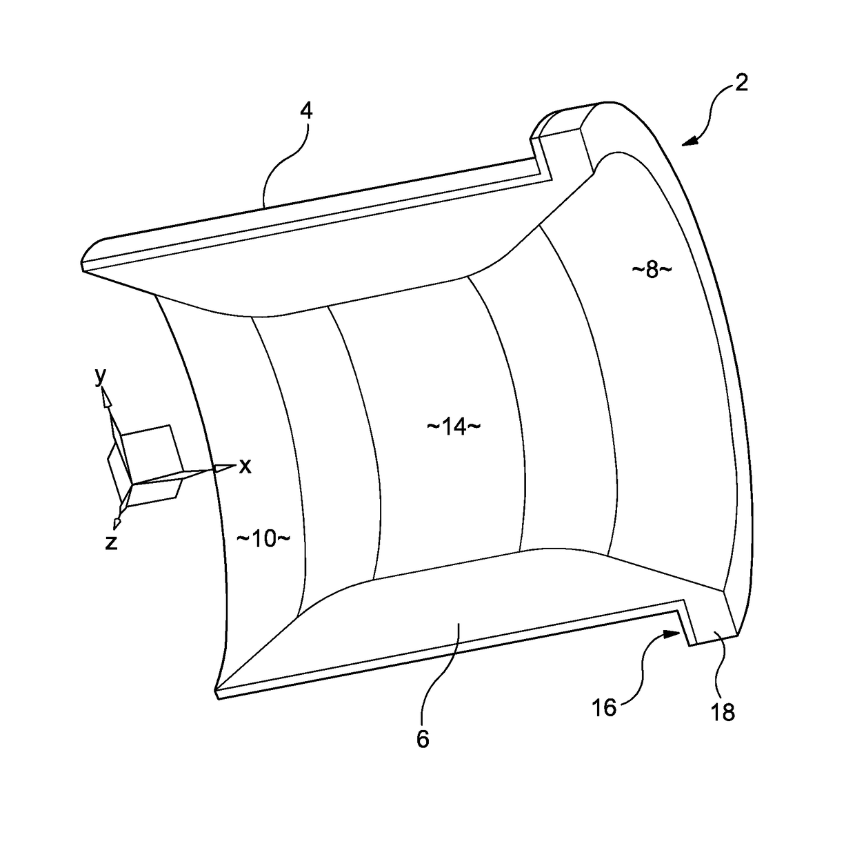
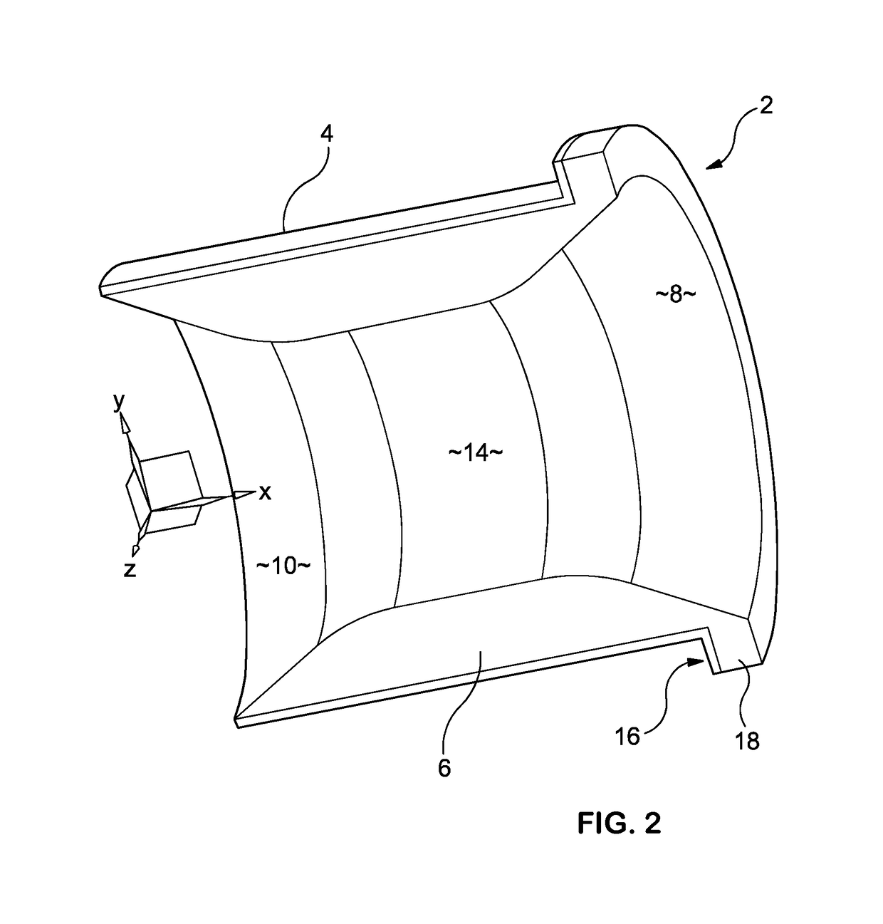
[0019]FIG. 2 is an isometric, cross-sectional schematic of an arrangement 2 comprising an acoustic insert 6 seated within an outer tube 4 which is fitted to the enclosure of a loudspeaker (not shown). The acoustic insert 6 and the outer tube 4 together form an open ended, cylindrical tube, with a first end 8 opening at the wall of the loudspeaker enclosure and a second end 10 inside the enclosure. The insert flares outwardly at the first and second ends, with a central portion 14 of smaller radius (around the X axis shown) than at the two ends. The first end of the outer tube 4 has a lip 16 which engages with the wall of the loudspeaker enclosure as is known in the art. The insert, which is made of low density foam material, is also formed with a matching lip 18, which seats on the lip 16 when the insert is fully inserted within the outer tube 4; this prevents the insert from being pushed too far inside the outer tube, and instead ensures that the insert 6 is in the correct longitud...


PUM


Abstract

An acoustic insert for lining a loudspeaker reflex port, the insert comprising an elongate hollow tube formed of a flexible material, having an outer wall sized and configured to seat within the port and an inner wall extending in the elongate direction, the inner wall having a circumference which varies along the length of the insert, When inserted in a port, the insert alters the port resonance so as to vary the acoustic perfoi mance of the loudspeaker.

Description

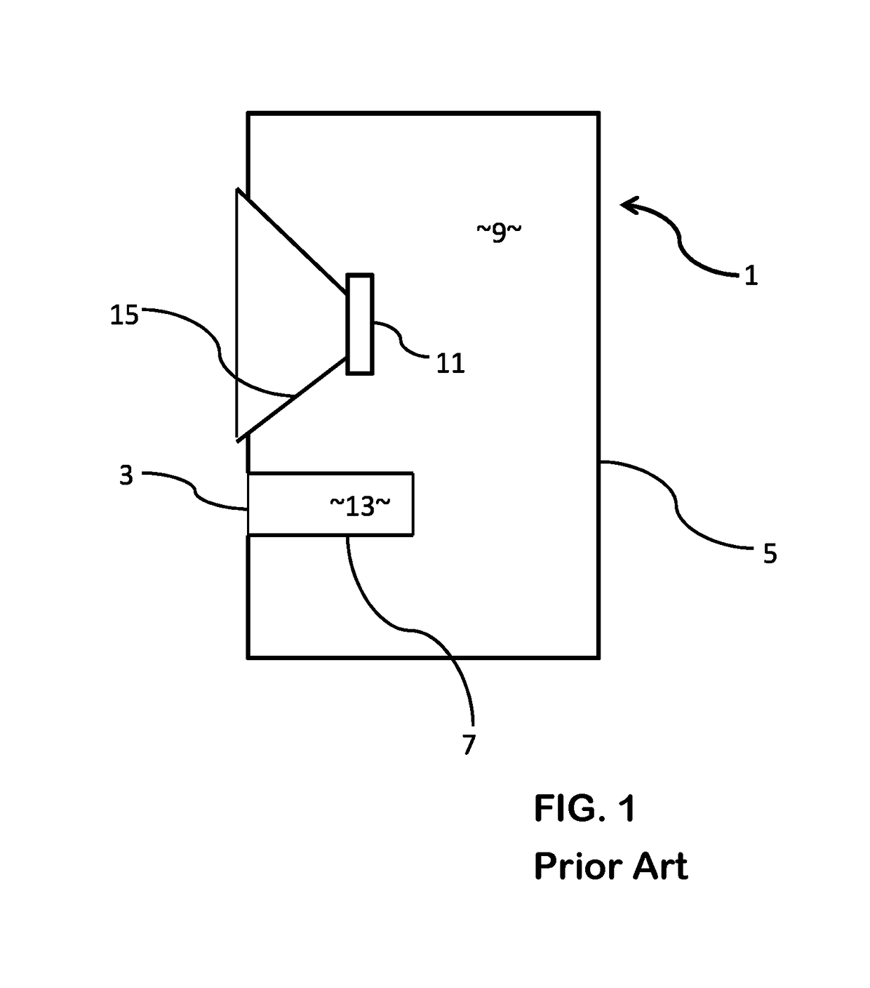
FIELD OF THE INVENTION[0001]This invention relates to reflex-type loudspeakers, and to liners or inserts for the vented port(s) of such loudspeakers.BACKGROUND ART[0002]A significant proportion of loudspeakers which are currently commercially available are of the type commonly known as bass reflex loudspeakers. A bass reflex system (also known as a ported, vented box or reflex port) is a type of loudspeaker enclosure that uses the sound from the rear side of the diaphragm to increase the efficiency of the system at low frequencies as compared to a typical closed box loudspeaker or an infinite baffle mounting. Referring to FIG. 1, a bass reflex loudspeaker 1 typically has one or more openings 3 in the loudspeaker enclosure 5 (called reflex ports or vents), each of which usually consists of a rigid pipe, duct or tube 7 (typically circular or rectangular in cross-section) mounted in the front or rear face of the loudspeaker enclosure 5, leading from the air volume 9 behind the driver 1...

Claims


Application Information

Patent Timeline
Patent Type & Authority Patents(United States)
IPC IPC(8): H04R1/28G10D13/02
CPCH04R1/2826H04R1/2819H04R1/2888G10D13/021G10D13/02
Inventor OCLEE-BROWN, JACK
Owner GP ACCOUSTICS (UK) LIMITED
Learn More