Radio reception system that can remove interference signal component signal component of another user from a reception signal

a radio reception system and interference signal technology, applied in the field of radio reception systems, can solve the problems of not being able to extract only the signal the conventional adaptive array b>11/b> cannot separate the signals of users b>1/b> and b>3/b>, so as to improve communication quality, improve communication quality, and improve communication quality

Inactive Publication Date: 2007-02-13
HERA WIRELESS
View PDF14 Cites 6 Cited by
  • Summary
  • Abstract
  • Description
  • Claims
  • Application Information

AI Technical Summary

Benefits of technology

[0024]Thus, the main advantage of the present invention is that, when a signal of a particular user is to be extracted from signals received from a plurality of users using a plurality of antennas, the interference component by an unrequired user signal component can be removed to improve communication quality.
[0025]Another advantage of the present invention is that, by providing a plurality of stages of user detection devices each having the ability to remove the interference component caused by an unrequired user signal component, the interference component can be removed in a plurality of stages to further improve communication quality.
[0026]A further advantage of the present invention is that the communication quality is improved together with the transmission capacity by removing the interference component caused by an unrequired user signal component from a desired user signal in a communication system of a large transmission capacity such as the CDMA communication system.

Problems solved by technology

However, the conventional adaptive array 11 cannot separate the signals of users 1 and 3.
Therefore, it was not possible to extract only the signal of user 1.

Method used


Image

  • Radio reception system that can remove interference signal component signal component of another user from a reception signal
  • Radio reception system that can remove interference signal component signal component of another user from a reception signal
  • Radio reception system that can remove interference signal component signal component of another user from a reception signal

Examples


second embodiment

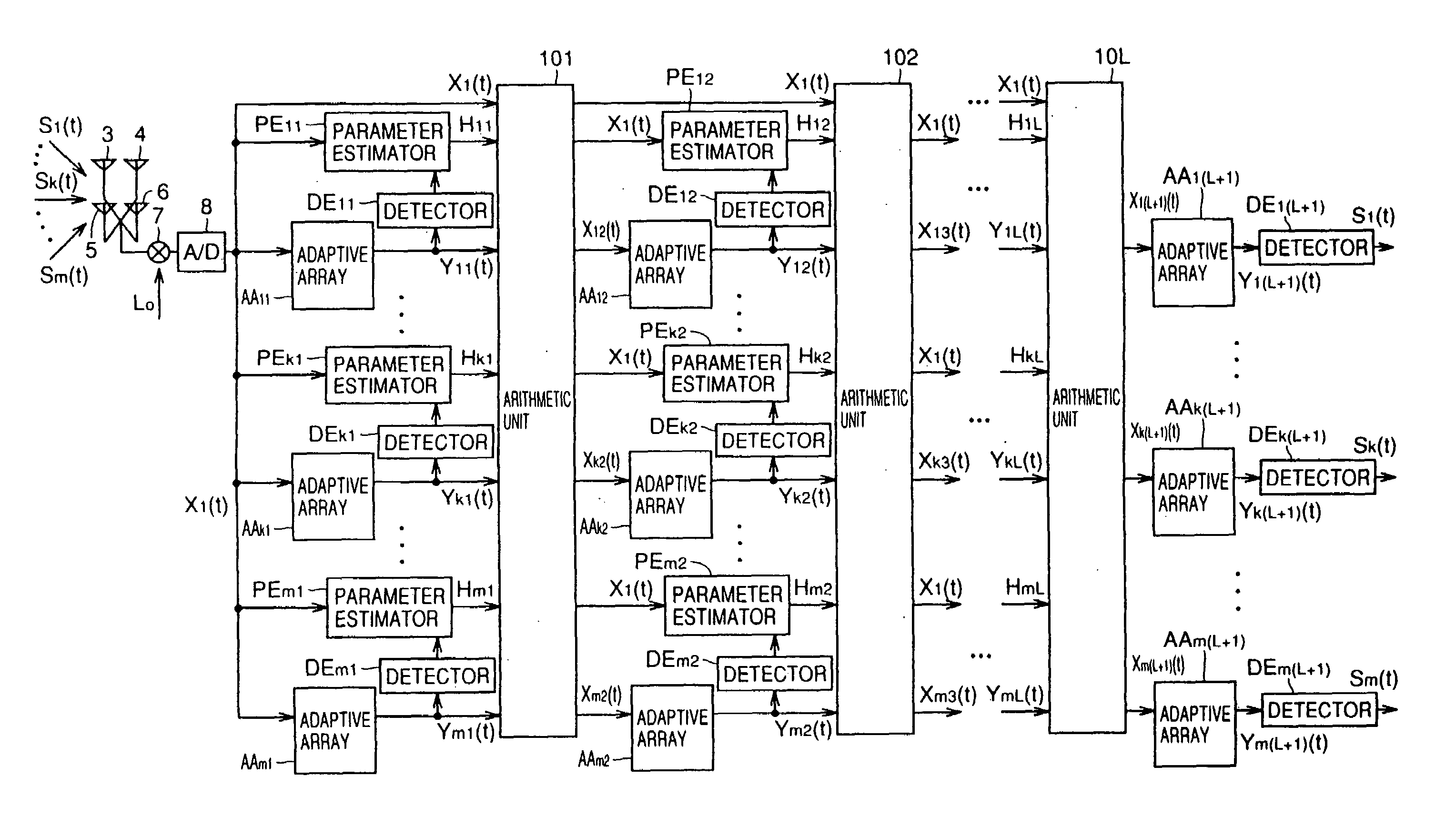
[0067]FIG. 3 is a block diagram showing the present invention. The embodiment of FIG. 3 further improves the property by providing in series a plurality of stages of user detection device, as well as detectors, each stage being formed of the adaptive arrays, the parameter estimators, and the arithmetic unit of FIG. 1 to reduce in a step-manner the ratio of the signal component of other users included in the user signal output from each stage. The operation of the circuit of each stage has been already described in detail with reference to FIGS. 1 and 2, and will not be repeated here.

third embodiment

[0068]FIG. 4 is a block diagram showing the present invention.

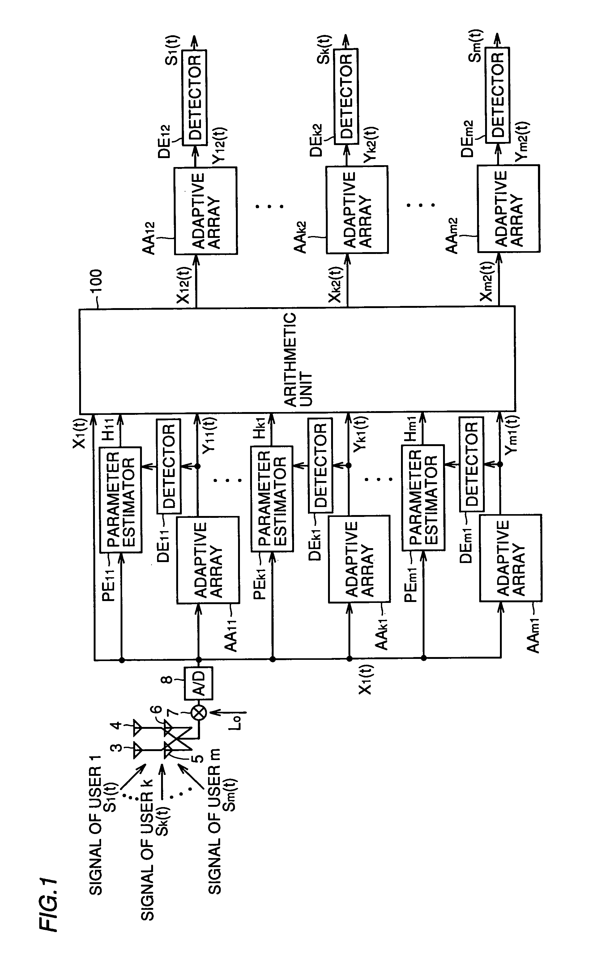
[0069]Referring to FIG. 4, input signal vector X1 (t) output from A / D converter 8 is applied to adaptive arrays AA11, . . . , AAk1, . . . , AAm1 and to arithmetic unit 201. Adaptive arrays AA11, . . . , AAk1, . . . , AAm1 extract and provide to arithmetic unit 201 corresponding user signals Y11 (t), . . . , Yk1 (t), . . . , Ym1 (t), respectively.

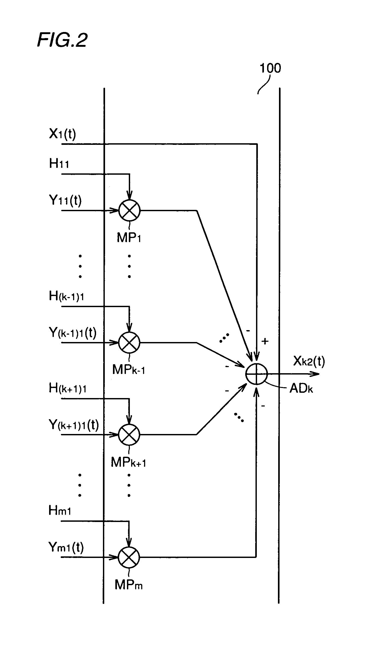
[0070]FIG. 5 is a specific block diagram of arithmetic unit 201 of FIG. 4. In FIG. 5, only the portion that carries out a signal process corresponding to user k is depicted out of the entire structure of arithmetic unit 201 for the sake of simplifying the description. The circuit of the same structure is provided corresponding to each of users 1, . . . , k−1, k+1, . . . , m besides user k.

[0071]The structure to generate input signal vector Xk2 (t) corresponding to user k will be described hereinafter with reference to FIG. 5. Arithmetic unit 201 includes parameter estimators PE1k1...

sixth embodiment

[0098]In the present sixth embodiment, a signal Sk+1 (t) of a more correct level of user k+1 can be extracted by using the signal vector obtained by multiplying the detected signal Yk (t) of user k by reception signal coefficient vector Hk output from the parameter estimator and subtracting the multiplied value from input signal vector Xk (t) used in the user detection device of the k-th stage, as input signal vector Xk+1 (t) of adaptive array AA(k+1)a of the user detection device of the (k+1)th stage.

[0099]FIG. 9 is a diagram to describe the operation of the parameter estimator used in each of the above embodiments. In a reception system with n antenna elements and m users connected in path multiplex, input signal vector Xk (t) of the k-th parameter estimator PEk1 connected in parallel is represented by the following equation (21).

Xk(t)=[x1k(t), x2k(t), . . . , xnk(t)]T   (21)

xjk(t)=hjkSk(t)+hjk+1Sk+1(t)+ . . . +hjmSm(t)+ . . . +nj(t), (k=1, 2, . . . , n)   (22)

[0100]A vector repre...


PUM


Abstract

In a receptive system of a base station according to the communication system of a PDMA, CDMA and the like, the reception signals from a plurality of users received on a plurality of antennas are frequency-converted by a frequency conversion circuit, and then converted into digital signals by an A / D converter to be applied to a DSP. The signal of a particular user is extracted from the input signal by an adaptive array. Also, the interference user signal component is removed by an interference canceller. Accordingly, the signal component of a desired user having the interference component caused by an unrequired user signal suppressed is output. Thus, the communication quality in a radio communication system such as a mobile communication system can be improved.

Description

BACKGROUND OF THE INVENTION[0001]1. Field of the Invention[0002]The present invention relates to radio reception systems. More particularly, the present invention relates to a radio reception system by a communication system such as the PDMA (Path Division Multiple Access) and the CDMA (Code Division Multiple Access) that can remove the interference signal component of another user from a reception signal.[0003]2. Description of the Related Art[0004]In the field of mobile communication systems such as portable telephones that have become extremely popular recently, various transmission channel allocation methods have been proposed to effectively use the frequencies. Some thereof are actually in practice.[0005]FIGS. 27A–27C show the channel arrangement in various communication systems of FDMA (Frequency Division Multiple Access), TDMA (Time Division Multiple Access), and PDMA. The systems of FDMA, TDMA, and PDMA will be described briefly with reference to FIGS. 27A–27C.[0006]Referrin...

Claims


Application Information

Patent Timeline
Patent Type & Authority Patents(United States)
IPC IPC(8): H04B1/69H01Q3/26H04B1/7107H04B7/08H04J13/00H04J99/00H04W16/28H04W88/08
CPCH04B7/0851H04B1/71075H04B1/71072
Inventor DOI, YOSHIHARU
Owner HERA WIRELESS
Why Eureka
Try Eureka