Indicator assembly with halo-free pointer

a technology of indicator assembly and pointer, which is applied in the direction of measuring apparatus components, instruments, fluid speed measurement, etc., can solve the problems of light leakage through the hole in the display face, and the halo effect is particularly problemati

Inactive Publication Date: 2007-02-20
YAZAKI NORTH AMERICA
View PDF28 Cites 4 Cited by
  • Summary
  • Abstract
  • Description
  • Claims
  • Application Information

AI Technical Summary

Benefits of technology

[0002]The present invention generally relates to illuminated indicator assemblies and more particularly to an illuminated indicator assembly wherein light leakage about the hub of a pointer is significantly reduced or eliminated altogether.
[0004]The halo effect is particularly problematic with non-black dial faces and in particular, dial faces with background colors that are relatively light in color such as white, cream or tan. Accordingly, it would be desirable to have an illuminated indicator assembly that significantly reduced or eliminated light leakage about the pointer.SUMMARY
[0007]In yet another form, the present teachings provide a method for reducing or eliminating a halo effect. The method includes: providing a display face having an opaque portion with a shaft aperture formed therethrough; providing a pointer with a hub portion and a boot portion, the boot portion being coupled to the hub portion and being formed of an opaque material; aligning a pointer to the shaft aperture such that the boot portion contacts the display face in a zone encircling the shaft aperture; and illuminating a lamp on a side of the display face opposite the boot portion.

Problems solved by technology

One drawback of the known illuminated indicator assembly arrangements concerns light leakage through the hole in the display face.
The halo effect is particularly problematic with non-black dial faces and in particular, dial faces with background colors that are relatively light in color such as white, cream or tan.

Method used


Image

  • Indicator assembly with halo-free pointer
  • Indicator assembly with halo-free pointer
  • Indicator assembly with halo-free pointer

Examples


Embodiment Construction

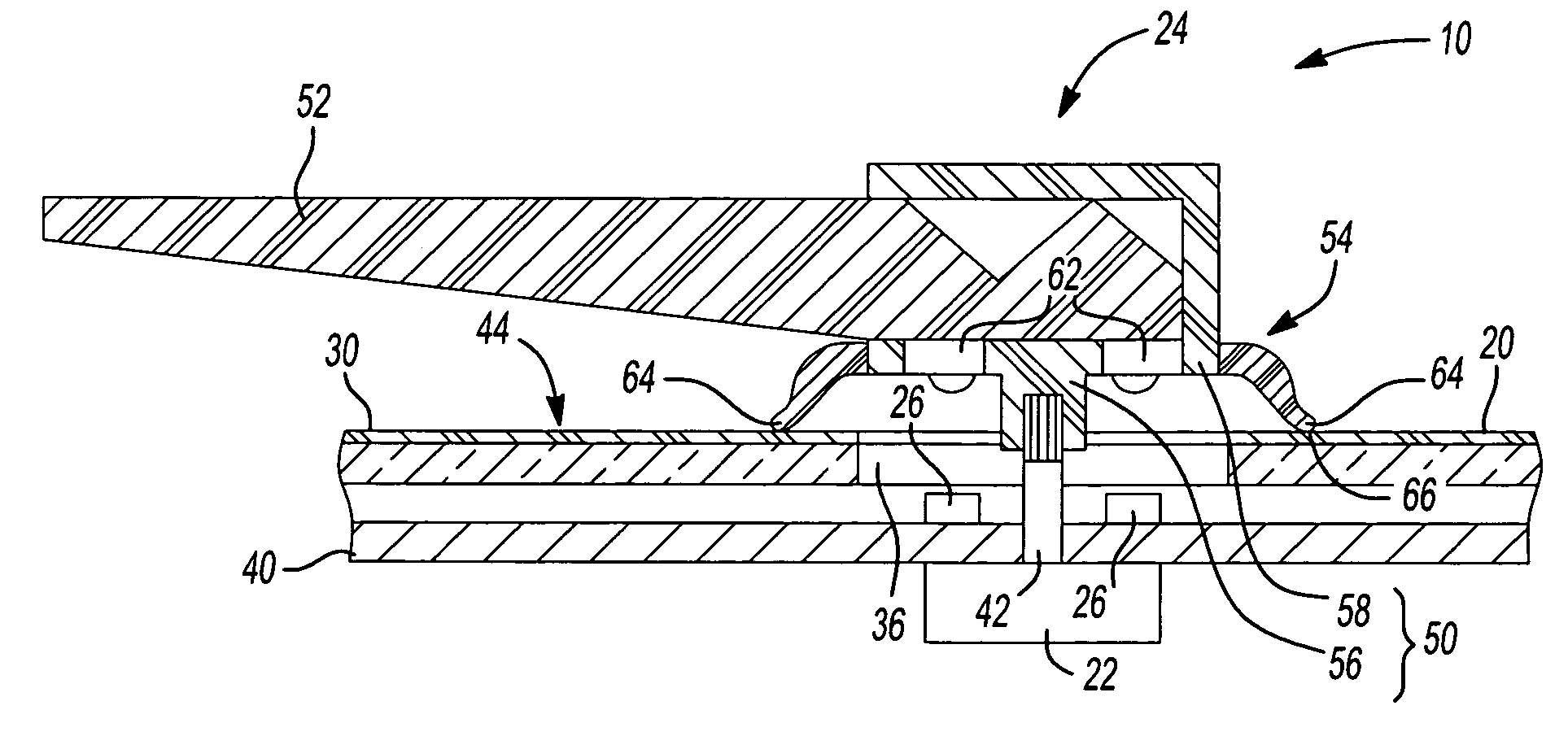
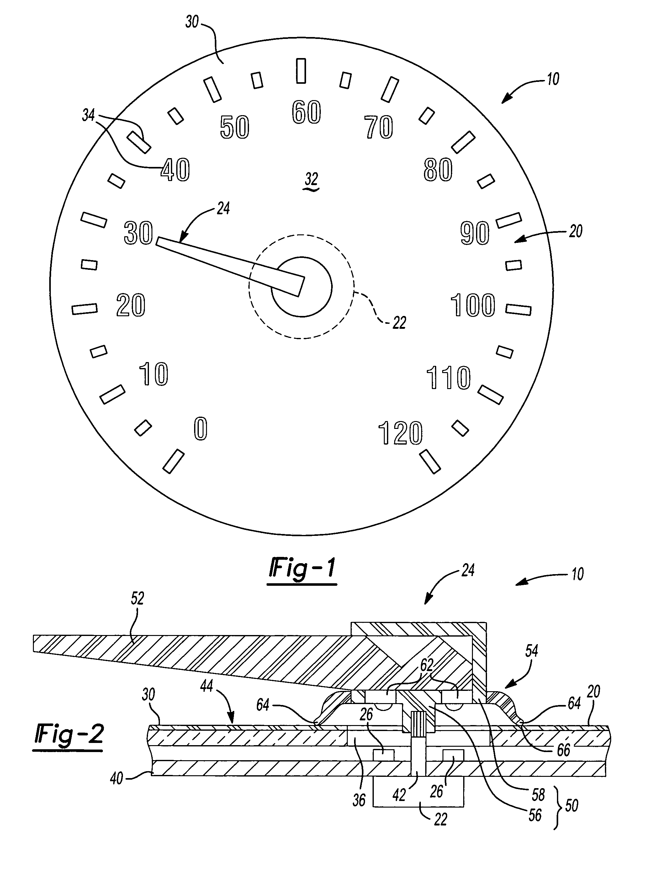
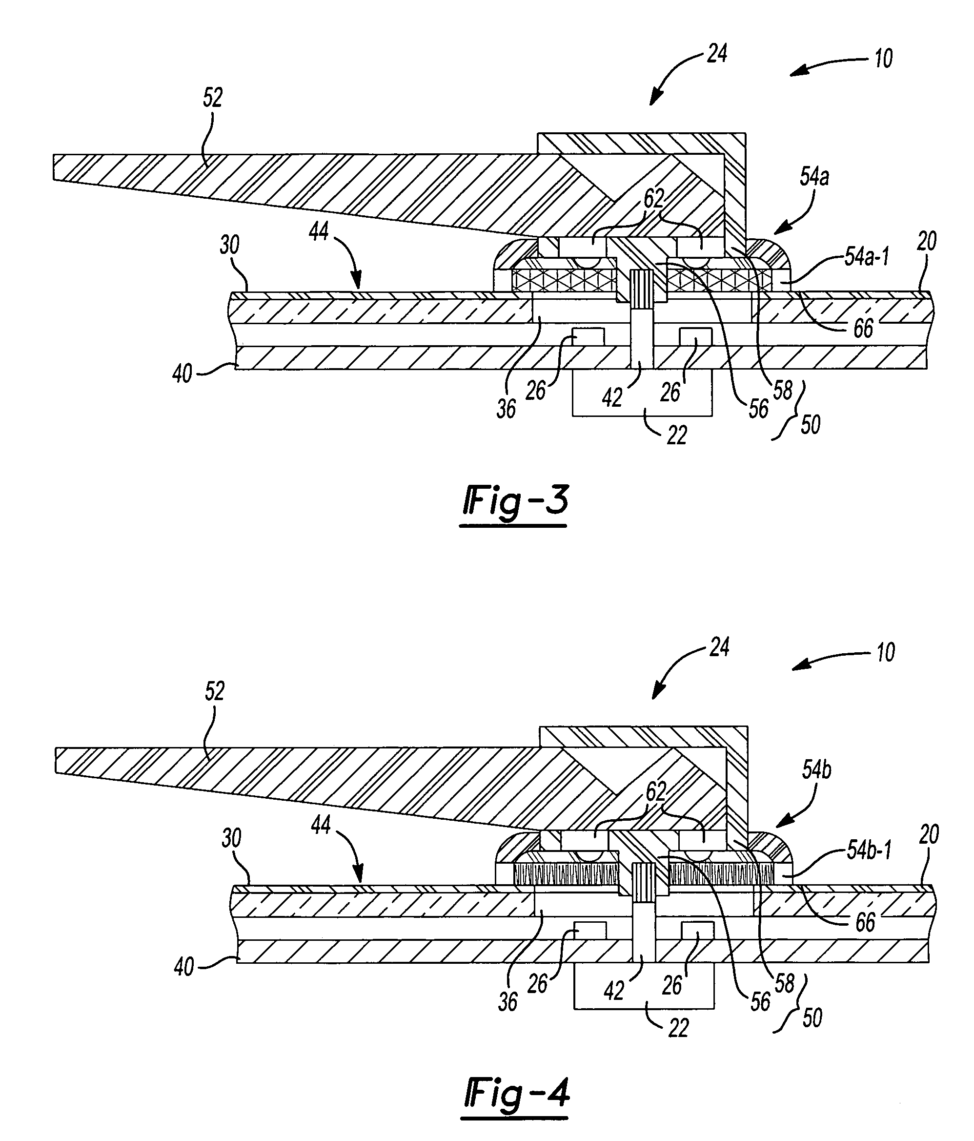
[0014]With reference to FIGS. 1 and 2 of the drawings, an indicator assembly constructed in accordance with the teachings of the present invention is generally indicated by reference numeral 10. The indicator assembly 10 can generally include a dial 20, a drive unit 22, a pointer 24 and a lamp 26. While the indicator assembly 10 is illustrated as being a speedometer, it will be appreciated that the teachings of the present invention have applicability to various other types of instruments, whether automotive or not, and as such, the particular example illustrated is not intended to be limiting in any way.

[0015]The dial 20 can include a dial face 30 with an opaque portion or background 32 and dial face indicia 34, which may be translucent. The background 32 can have any coloration, including a non-black color such as white, cream, tan or another relatively light color. A shaft aperture 36 can be formed through the background 32.

[0016]The drive unit 22 can include a motor, such as a s...


PUM


Abstract

An indicator assembly with a dial face, a pointer and a lamp. The dial face has an opaque portion and defines a shaft aperture. The pointer has a connecting portion, a pointer portion and an opaque boot portion. The connecting portion is disposed in-line with the aperture. The pointer portion is coupled to and extends radially outwardly from the connecting portion. The boot portion extends about the connecting portion and contacts the dial face in a zone that encircles the aperture. The lamp is disposed rearwardly of the dial face and provides a source of light. A method for reducing or eliminating a halo effect is also provided.

Description

CROSS-REFERENCE TO RELATED APPLICATIONS[0001]This application is a continuation-in-part of U.S. patent application Ser. No. 11 / 029,961, which was filed on Jan. 5, 2005 now U.S. Pat. No. 6,983,717.INTRODUCTION[0002]The present invention generally relates to illuminated indicator assemblies and more particularly to an illuminated indicator assembly wherein light leakage about the hub of a pointer is significantly reduced or eliminated altogether.[0003]Illuminated indicator assemblies having a rotating pointer are known in the art. In such instruments, the pointer is driven by a shaft that extends through a hole in a display face or member. One drawback of the known illuminated indicator assembly arrangements concerns light leakage through the hole in the display face. More specifically, light leaking through the hole in the display face tends to illuminate the hub of the pointer which is known in the art as producing a “halo effect”.[0004]The halo effect is particularly problematic wi...

Claims


Application Information

Patent Timeline
Patent Type & Authority Patents(United States)
IPC IPC(8): G01D11/28
CPCG01D11/28G01D13/265Y10S116/36B60K2370/6992
Inventor FONG, CHINGYAMAGUCHI, KAZUHIKO
Owner YAZAKI NORTH AMERICA
Why Eureka
Try Eureka