Chisel

a technology of chisels and supports, applied in the field of chisels, can solve the problems of inconvenient and economical manufacturing of support parts, and achieve the effect of reducing friction between the channel chisel and the base of the channel

Inactive Publication Date: 2007-02-20
BLACK & DECKER INC
View PDF35 Cites 20 Cited by
  • Summary
  • Abstract
  • Description
  • Claims
  • Application Information

AI Technical Summary

Benefits of technology

[0007]A channel chisel having at least one support member protruding from a side of the channel chisel that is adapted to abut and slide along a base of a channel to support the channel chisel has the advantage that there is no contact between the channel chisel and the upper surfaces of the work piece being cut and so there will be no damage caused to the edges of the channel. When the support member abuts the base of the channel the channel chisel can also be tilted forward, or backward, about the support member to change the angle at which the cutting edge cuts the work piece. This enables the user to increase, or decrease, the depth of channel cut in the work piece. Whilst the depth of cut can be altered, the contact between the support member and the base of the channel is substantially unchanged. A support member protruding from the underside of the channel chisel also provides the advantage of a greater range of cutting depths, as there is no part of the channel chisel in contact with the upper surface of the channel to limit the depth to which the channel chisel can cut into the work piece.
[0009]Alternatively, the support member can be made separately from, but permanently fixed to, the channel chisel by welding. This allows intricate shapes of support member to be made that may not be possible, or economical, if formed integrally with the channel chisel. For example, a support member with a roller, or bearing, adapted to reduce friction between the channel chisel and the base of the channel is a possible variant.
[0010]Another alternative is to detachably fix the support member to the channel chisel with a fastening means, like, for example, a screw or a dowel. This allows a support member adapted for cutting channels of a certain range of depths to be exchanged for another support member adapted for cutting a different range of depths. If the support member is fastened to the channel chisel then preferably there is an interlocking fit between channel chisel and support member, in addition to the fastening means, that prevents sheer or tension forces from acting upon the fastening means that could result in its failure and inadvertent removal of the support member.
[0012]The support member may have a rounded surface for abutment with the base of the channel. This allows the channel chisel to be tilted smoothly backward and forward. Preferably, the support member has a rounded hump shape in longitudinal cross-section. This shape gives a good range of tilt angles for the channel chisel.

Problems solved by technology

This allows intricate shapes of support member to be made that may not be possible, or economical, if formed integrally with the channel chisel.

Method used


Image

  • Chisel
  • Chisel

Examples


Embodiment Construction

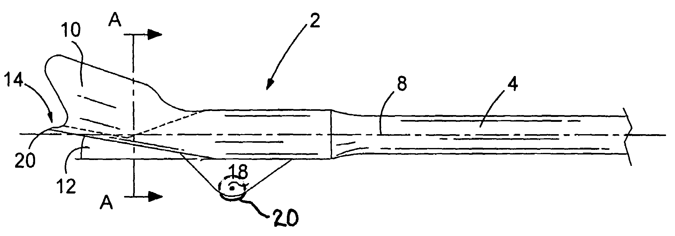
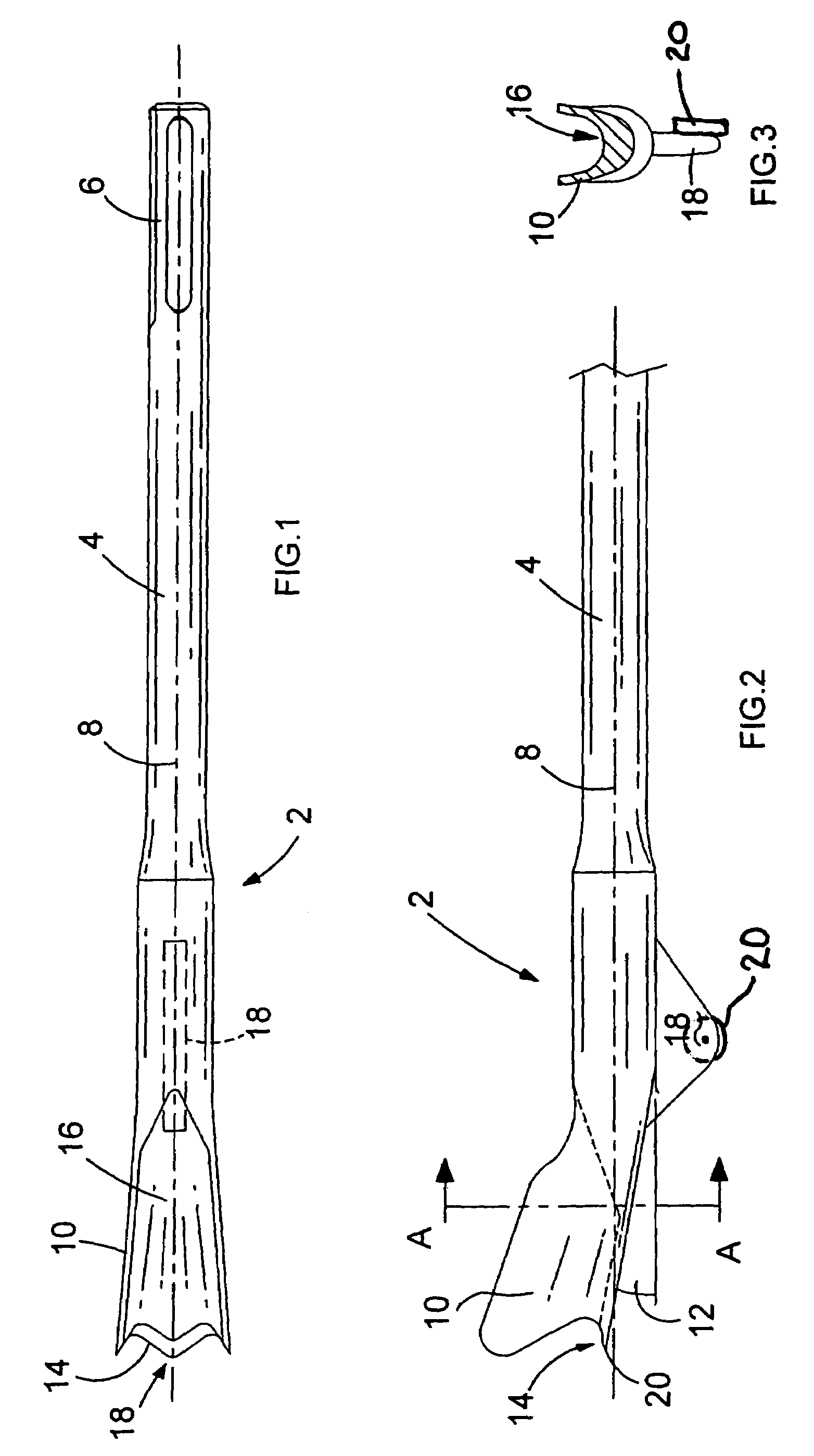
[0018]A channel chisel 2 comprises an elongate shaft 4 with a shank 6 at one end for connection to the output of a hammer apparatus (not shown). The shaft 4 and the shank 6 have a longitudinal axis 8. A tip 10 is formed at the other end of the shaft 4. The tip 10 is slightly inclined by an acute angle 12 in relation to the longitudinal axis 8. The tip has a cutting edge 14. As is shown FIG. 3, the tip 10 is U-shaped in cross-section to form a flute 16 within the confines of the tip 10. The flute 16 is for transporting debris cut from a work piece rearward from the cutting edge 14. A support member 18 protrudes radially outward from the underside of the trough of the U-shaped tip 10. The support member 18 may include a roller or bearing 20 adapted to reduce friction between the channel chisel 10 and the base of the channel.

[0019]To cut a channel in the surface of concrete, or the like, first the shank 6 is connected to the output of a hammer apparatus (not shown). Next, the user of t...


PUM

PropertyMeasurementUnit
angleaaaaaaaaaa
frictionaaaaaaaaaa
shapeaaaaaaaaaa

Abstract

A channel chisel for forming a channel in a work piece, the channel chisel comprising a shaft having a longitudinal axis, a tip at one end of the shaft, wherein the tip has a cutting edge for cutting a work piece and a flute for removal of debris cut from a work piece, and at least one support member protruding from a side of the channel chisel, characterised in that the support member is adapted to abut and slide along a base of a channel to support the channel chisel in use, wherein support provided by the support member permits the channel chisel to pivot about the support member to change the angle at which the cutting edge cuts a work piece.

Description

BACKGROUND OF THE INVENTION[0001]The present invention relates to chisels, and relates particularly, but not exclusively, to chisels for cutting a channel.[0002]Often there is a need to form a channel in a work piece into which cables or pipes can be laid. The usual work piece is a concrete or similar hard ceramic surface. The ideal choice of tool is a chisel specifically shaped to cut such a channel, hereinafter referred to as a “channel chisel”. In use the channel chisel can be connected to a reciprocating hammer apparatus like, for example, a portable power tool called a hammer, which repeatedly hits the channel chisel to transmit impact forces to it.[0003]EP0519493 discloses a channel chisel comprising a shaft for insertion into the hammer and a tip that is inclined in relation to the axis of the shaft. The tip is U-shaped in cross-section and includes a flute to facilitate the removal of debris cut from the channel. A wing is formed on each side of the shaft. The wings are fold...

Claims


Application Information

Patent Timeline
Patent Type & Authority Patents(United States)
IPC IPC(8): B25D17/02B28D1/26
CPCB25D17/02B25D2250/355
Inventor ROMPEL, MARKUS
Owner BLACK & DECKER INC
Why Eureka
Try Eureka