Zoned thermal monitoring

Active Publication Date: 2007-02-20
ADVANCED MICRO DEVICES INC
View PDF8 Cites 23 Cited by
  • Summary
  • Abstract
  • Description
  • Claims
  • Application Information

AI Technical Summary

Problems solved by technology

If the temperature of an integrated circuit, or a portion of an integrated circuit, rises above a certain maximum temperature, damage can result.

Method used


Image

  • Zoned thermal monitoring
  • Zoned thermal monitoring
  • Zoned thermal monitoring

Examples


Embodiment Construction

)

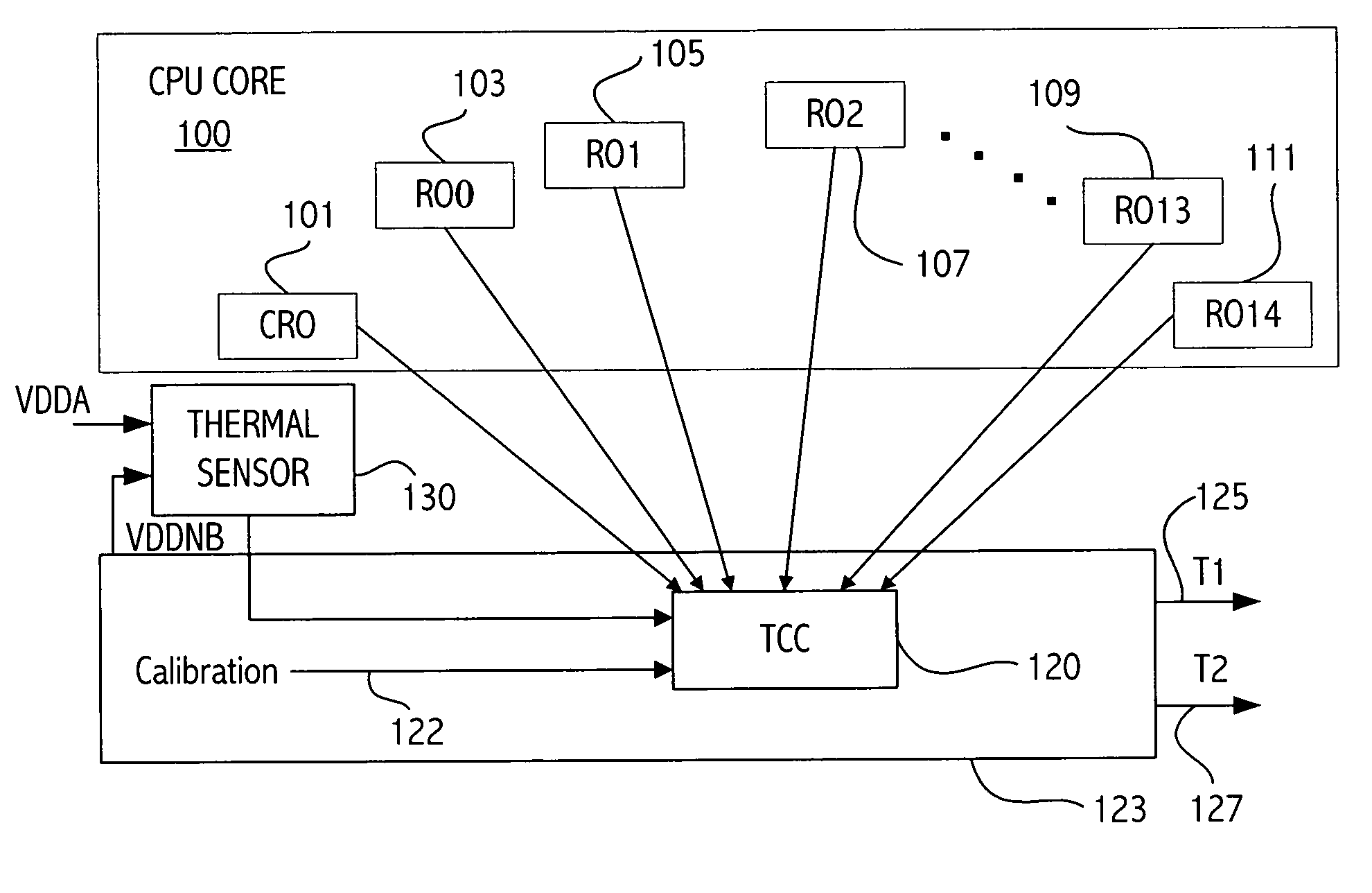
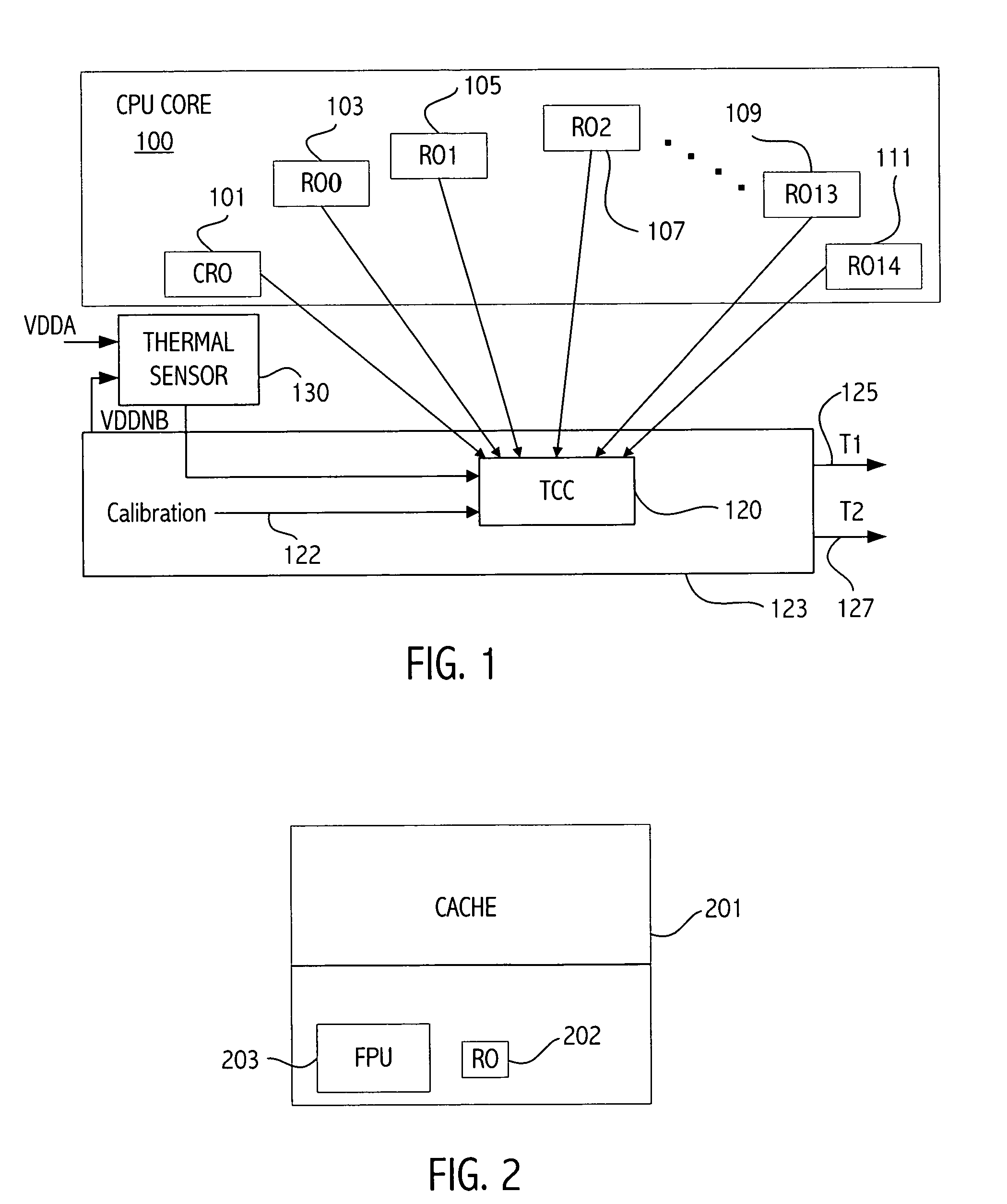
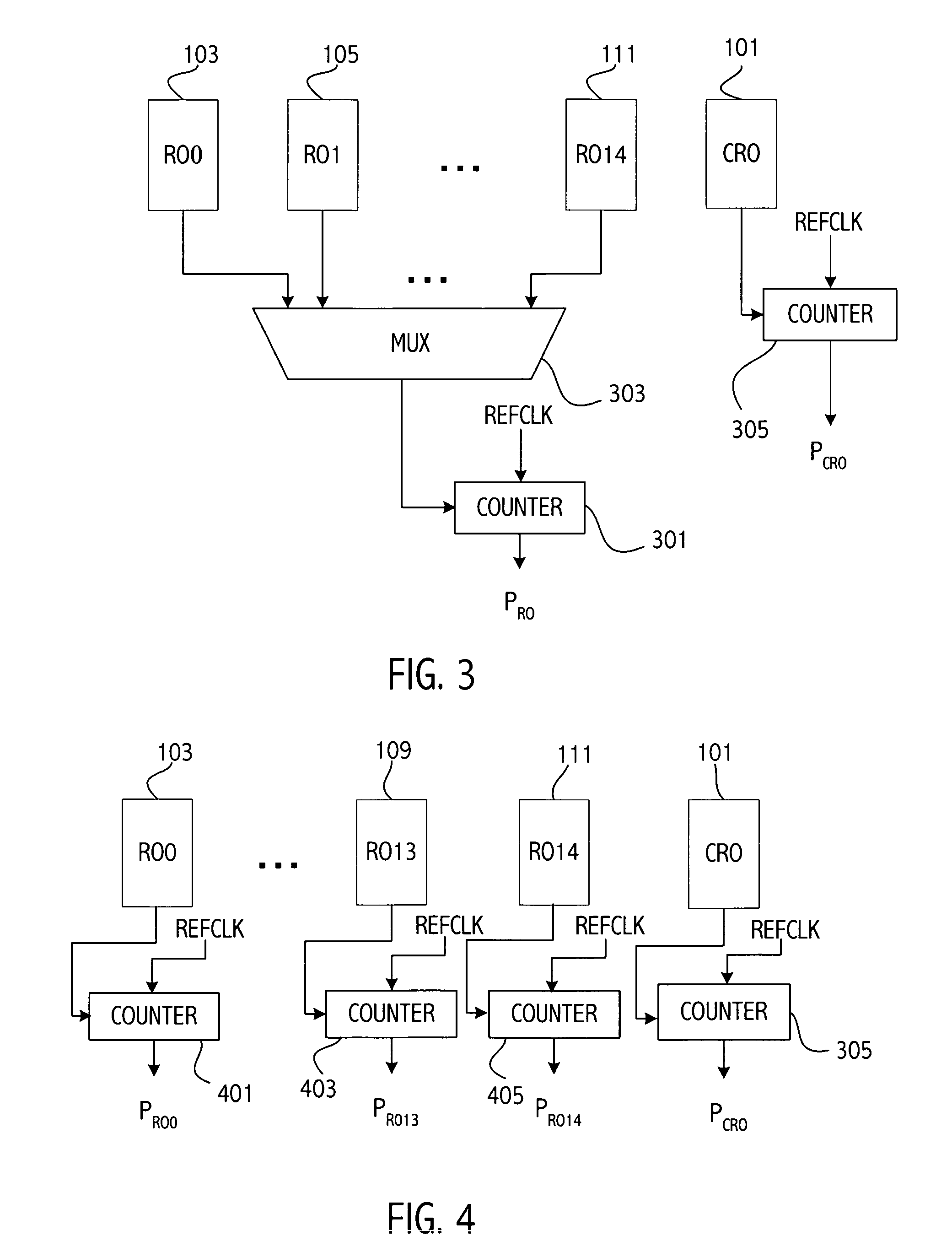
[0018]Referring to FIG. 1, illustrated is an exemplary thermal architecture for a microprocessor according to an embodiment of the invention. The microprocessor includes the CPU core 100. The CPU core 100 includes a plurality of ring oscillators whose oscillation frequency is used to determine temperatures of regions of the CPU core adjacent to the ring oscillators. The thermal architecture includes a correlation ring oscillator (CRO) 101 and ring oscillators (RO) 103–111. In the illustrated embodiment there are 15 ring oscillators (RO0–RO14) in addition to the correlation ring oscillator CRO 101. Other embodiments may have more or less ring oscillators. The ring oscillators RO0–RO14 are disposed in various locations in the CPU core in order to measure the temperature at a variety of locations in the integrated circuit. Large thermal gradients may be present on the die. For example, regions of the die may differ by, e.g., 50° C. Thermal energy spreads relatively slowly and therefor...


PUM

PropertyMeasurementUnit
cycle timeaaaaaaaaaa
temperatureaaaaaaaaaa
oscillation frequencyaaaaaaaaaa

Abstract

An integrated circuit includes a first temperature sensing device providing an indication of a sensed temperature, a correlation oscillator circuit positioned adjacent to the first temperature sensing device, a plurality of other oscillator circuits, and storage locations storing calibration factors associated with at least the first temperature sensing device and the plurality of other oscillator circuits. A temperature calculation circuit determines temperatures of various locations in the integrated circuit. Each of the temperatures is determined according to an oscillation frequency of a respective one of the other oscillators, the oscillation frequency of the correlation ring oscillator, the temperature of the first temperature sensing device, and one or more stored calibration factors.

Description

BACKGROUND[0001]1. Field of the Invention[0002]This invention relates to integrated circuit circuits and more particularly to thermal monitoring of integrated circuits.[0003]2. Description of the Related Art[0004]Integrated circuits have typically measured temperature at a single point on an integrated circuit die, often using an analog (diode) structure. That one measured temperature was considered to be representative of the entire die area. However, in integrated circuits such as microprocessors the geometries utilized in the integrated circuit have decreased, speed has increased and power utilization has increased. The area around regions that are densely populated with switching transistors tends to be much hotter than the average die temperature resulting in a thermal gradient across the die. In fact areas of the die can be 25° C. hotter than other areas of the die in 130 nm technology at 90 W. The thermal gradient will be even greater as geometries continue to decrease and po...

Claims


Application Information

Patent Timeline
Patent Type & Authority Patents(United States)
IPC IPC(8): G01K7/00G01K1/08
CPCG01K7/42G01K7/425G01K15/00H01L23/34H01L2924/0002H01L2924/00
Inventor BIENEK, MICHAEL D.HEWITT, LARRYLIU, HUINING
Owner ADVANCED MICRO DEVICES INC
Why Eureka
Try Eureka