
Connecting mechanism for a battery case and a body of a portable electronic device

a technology of connecting mechanism and battery case, which is applied in the direction of cell components, casings/cabinets/drawers, electric apparatus casings/cabinets/drawers, etc., can solve the problems of battery case being liable to be misplaced or accidentally damaged, and the battery case being easy to be damaged, so as to avoid the risk of misplacing the battery case and convenient changing the battery of the devi

Active Publication Date: 2007-02-20
FIH (HONG KONG) LTD +1
View PDF5 Cites 60 Cited by
  • Summary
  • Abstract
  • Description
  • Claims
  • Application Information

AI Technical Summary

Benefits of technology

The present invention provides a connecting mechanism for a battery case and a body of a portable electronic device. This mechanism allows users to conveniently change the battery without risking misplacing the battery case. The mechanism includes a main body, a connecting member, a cover, and a shaft. The connecting member has two mounting portions, and the cover has a sliding space. The shaft extends through the mounting portions and is received in the receptacle, making the connecting member rotatable relative to the main body. The cover is both rotatable and slidable relative to the main body, and need not be detached from the main body. This mechanism simplifies the battery replacement process and improves the overall user experience of the portable electronic device.

Problems solved by technology

Nevertheless, in general, a good deal of force needs to be exerted on the battery case for it to be detached.
The battery case is easily damaged if excessive force is applied, both in the process of detaching the battery case and in the process of attaching the battery case.
Therefore, the battery case is liable to be misplaced or accidentally damaged.
All the above-described difficulties cause the user undue inconvenience.

Method used


Image

  • Connecting mechanism for a battery case and a body of a portable electronic device
  • Connecting mechanism for a battery case and a body of a portable electronic device
  • Connecting mechanism for a battery case and a body of a portable electronic device

Examples


Embodiment Construction

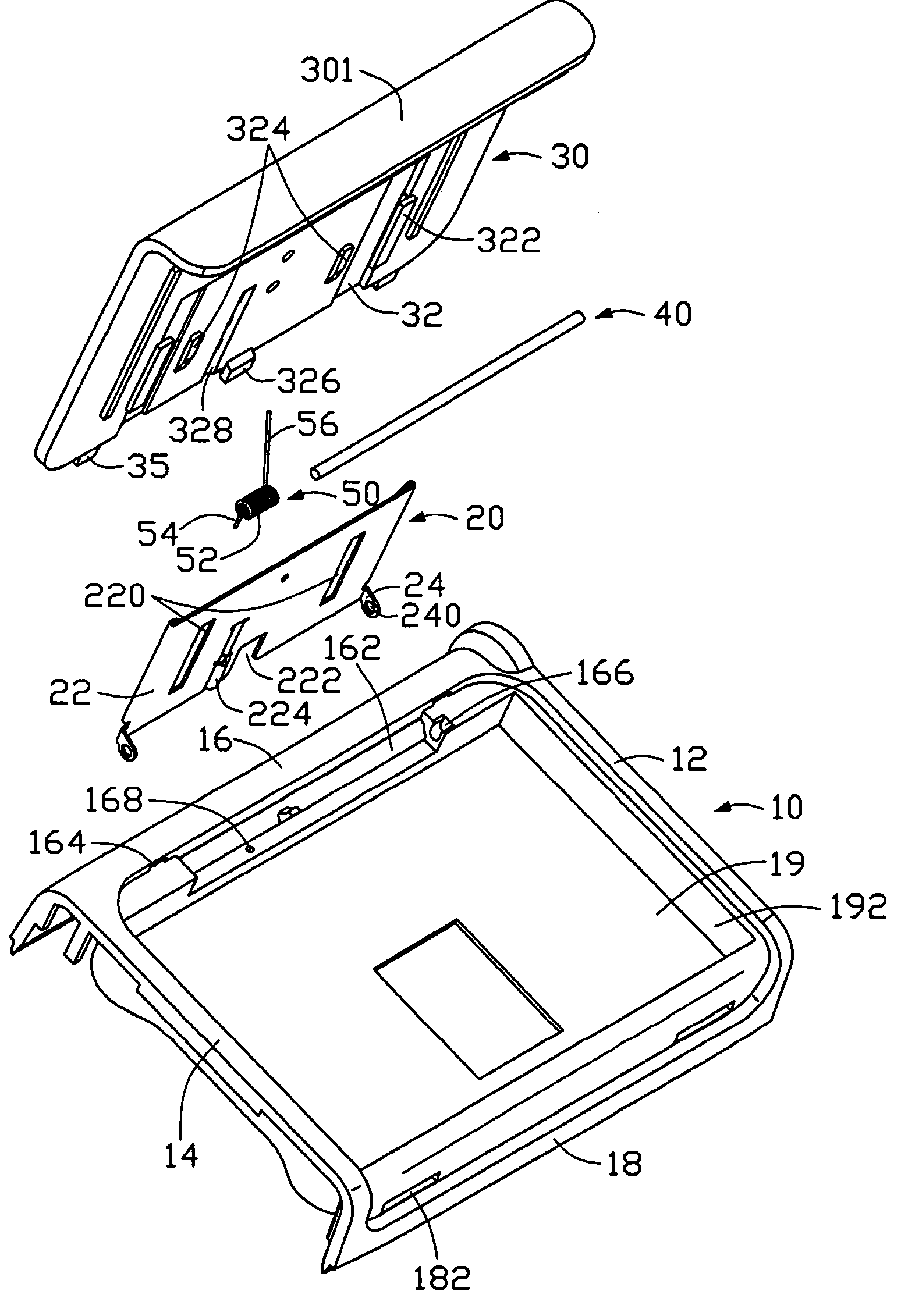
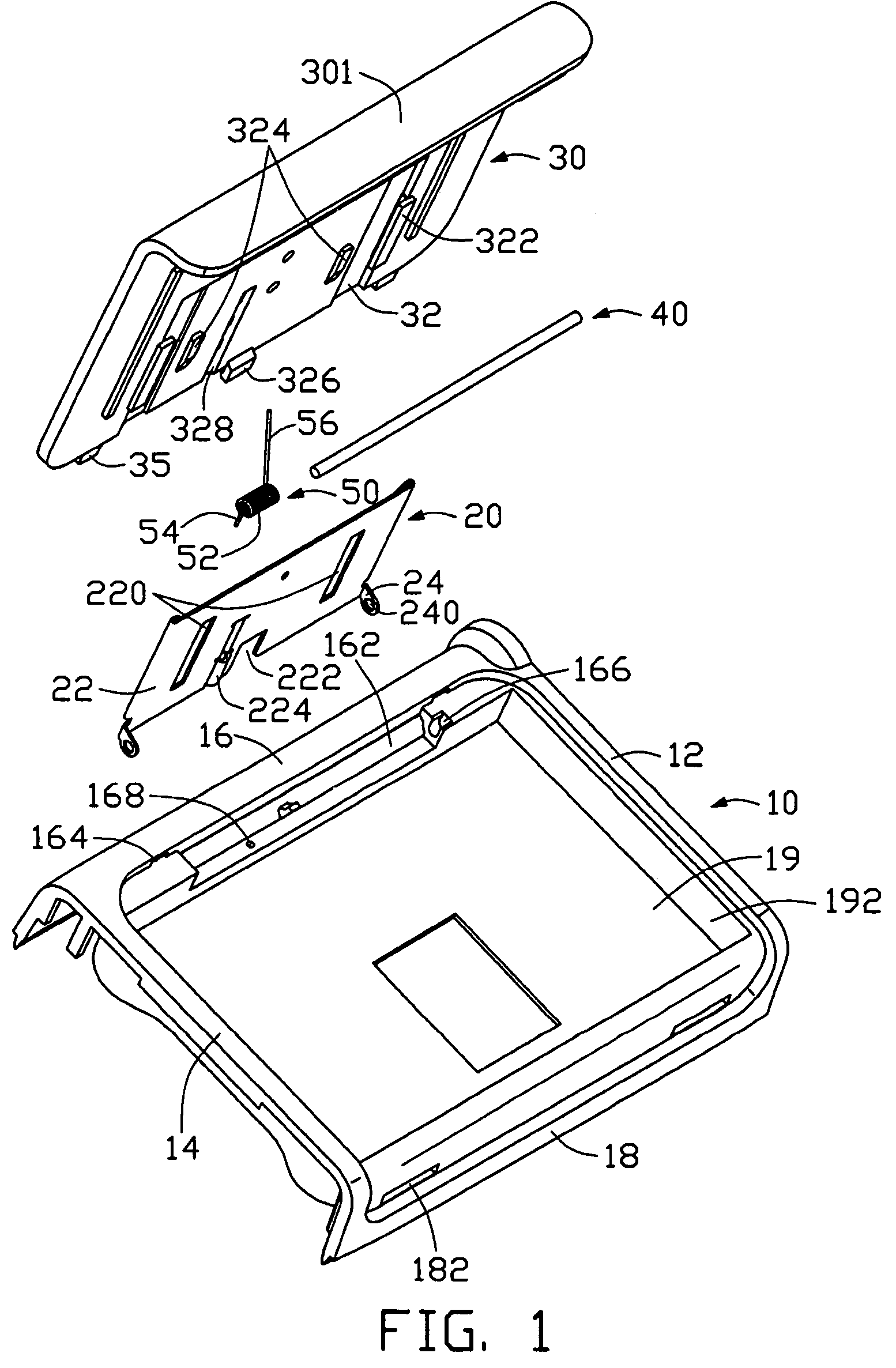
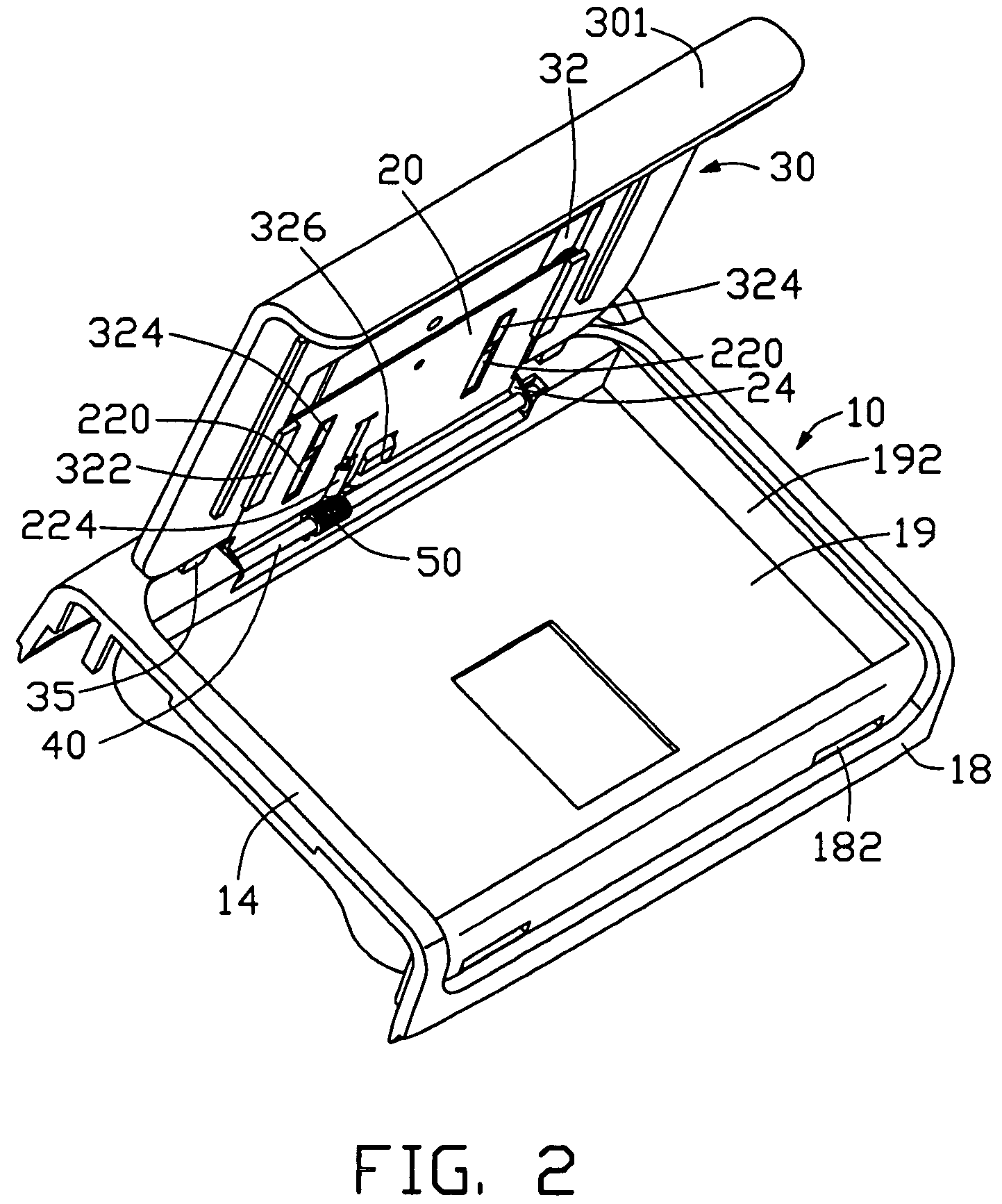
[0017]Referring to FIGS. 12, the preferred embodiment of a connecting mechanism for a battery case and a body of a portable electronic device comprises a main body 10, a connecting member 20, a cover 30, a shaft 40 and a spring member 50.

[0018]The main body 10 includes an upper sidewall 12, a lower sidewall 14, a left sidewall 16, and a right sidewall 18. The upper sidewall 12, the lower sidewall 14, the left sidewall 16 and the right sidewall 18 cooperatively form a generally rectangular compartment (not labeled). The main body 10 further includes a partition 19 disposed in the compartment; thereby forming an upper recessed portion 192 for receiving a battery (not shown) of the portable electronic device, and a lower containing portion 194 (see FIG. 3) for housing electronic components of the portable electronic device such as a printed circuit board. The left sidewall 16 has a receptacle 162 and a pair of spaced sockets 164. The shaft 40 is received in the receptacle 162. The rece...


PUM

PropertyMeasurementUnit
poweraaaaaaaaaa
forceaaaaaaaaaa
timeaaaaaaaaaa

Abstract

A connecting mechanism for a battery case and a main body of a portable electronic device includes a main body (10), a connecting member (20), a cover (30), and a shaft (40). The main body has a receptacle (162), and a recessed portion (192) for receiving the battery case. The connecting member has a body (22) and one or more mounting portions (24). The cover defines a sliding space. The shaft extends through the mounting portions and is received in the receptacle. Thus the connecting member is rotatable relative to the main body about the shaft. The connecting member is received in the sliding space and can slide along the sliding space relative to the cover. Thus the cover is both rotatable and slidable relative to the main body, and need not be detached from the main body.

Description

BACKGROUND OF THE INVENTION[0001]1. Field of the Invention[0002]This invention relates in general to portable electronic devices, and more specifically to a hinge-like connecting mechanism for a battery case and a body of a portable electronic device. This application is related to a contemporarily filed application titled “BATTERY COVER ASSEMBLY FOR PORTABLE ELECTRONIC DEVICE”. and having the same assignee.[0003]2. Prior Art[0004]Portable electronic devices, such as mobile phones and personal digital assistants, are in widespread use around the world. These devices are provided with power via batteries, with a battery being removably received in a main body of the device.[0005]For example, the Alcatel Corporation OT310 mobile phone has a pair of holders at an end of a battery case thereof, and a pin at an opposite end of the battery case. Corresponding to the battery case, the mobile phone has a pair of slots at an end of a main body thereof, and a hole at an opposite end of the ma...

Claims


Application Information

Patent Timeline
Patent Type & Authority Patents(United States)
IPC IPC(8): H05K7/14H05K7/18H01M2/10
CPCH04M1/0262H01M2/1066Y02E60/10
Inventor QIN, SHUI YUANCHEN, CHIA-HUALEE, YU-CHIEHHE, JIANG YUANHU, LINLI, CHANGZHI
Owner FIH (HONG KONG) LTD
Learn More