Anchoring device for a corrosion-resistant tension member, particularly an inclined cable for a cable-stayed bridge

a tension member and corrosion-resistant technology, which is applied in the direction of bridges, bridge structural details, girders, etc., can solve the problems of deformation of sealing plates and damage, and achieve the effect of simplifying the replacement of individual strands, saving energy, and avoiding additional energy expenditur

Inactive Publication Date: 2007-02-27
DYWIDAG SYST INT GMBH
View PDF17 Cites 16 Cited by
  • Summary
  • Abstract
  • Description
  • Claims
  • Application Information

AI Technical Summary

Benefits of technology

[0011]It is therefore an object of this invention to provide a simpler and more economical means for a seal of an anchoring area of a tension member of this kind, which allows sealing plates to breathe without additional expenditure of energy, and thus a more simplified replacement of individual strands.
[0012]A primary benefit of the invention is that the sealing plates are compressed by an additionally arranged pressure plate, and are thus put into a three-dimensional state of tension. Once the perforated disk arranged thereafter is locked in the anchor body, the position of the strands remains parallel even during squeezing and compression of the sealing plates. After the threaded bolts, which extend through the pressure plate, the sealing plates and the anchor plate are loosened, and the sealing plates are able to pass freely through the elastic extension path and return to their original position so that individual strands can be replaced without causing damage to the sealing plates and without having to loosen the entire wedge anchoring, due to the cylindrical shape of the anchor tube.

Problems solved by technology

Therefore, a replacement of individual strands requires the dismantling of the entire anchor plate; otherwise there is the danger that the deformed sealing plate is damaged when the strands are pulled.

Method used


Image

  • Anchoring device for a corrosion-resistant tension member, particularly an inclined cable for a cable-stayed bridge
  • Anchoring device for a corrosion-resistant tension member, particularly an inclined cable for a cable-stayed bridge
  • Anchoring device for a corrosion-resistant tension member, particularly an inclined cable for a cable-stayed bridge

Examples


Embodiment Construction

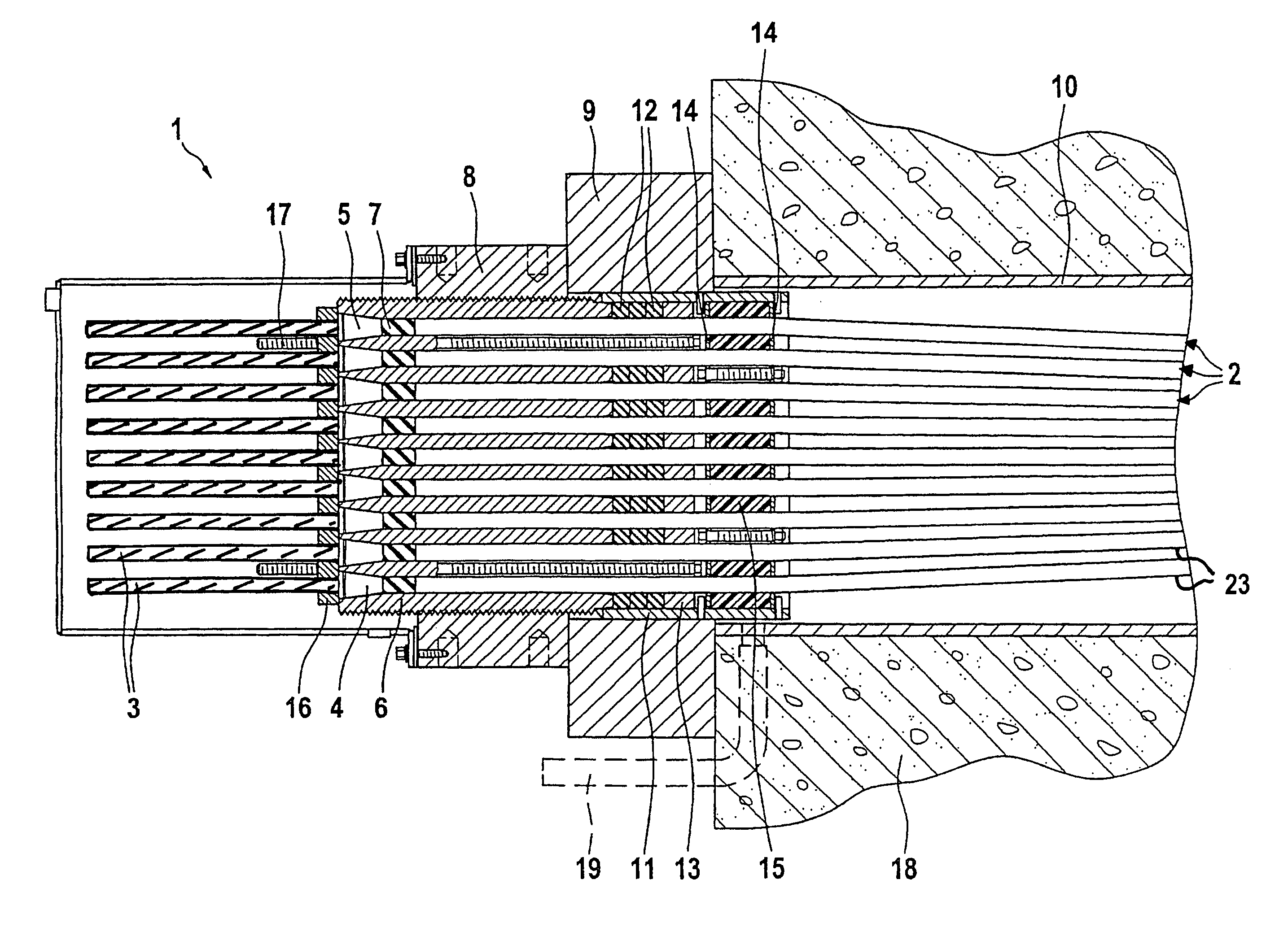
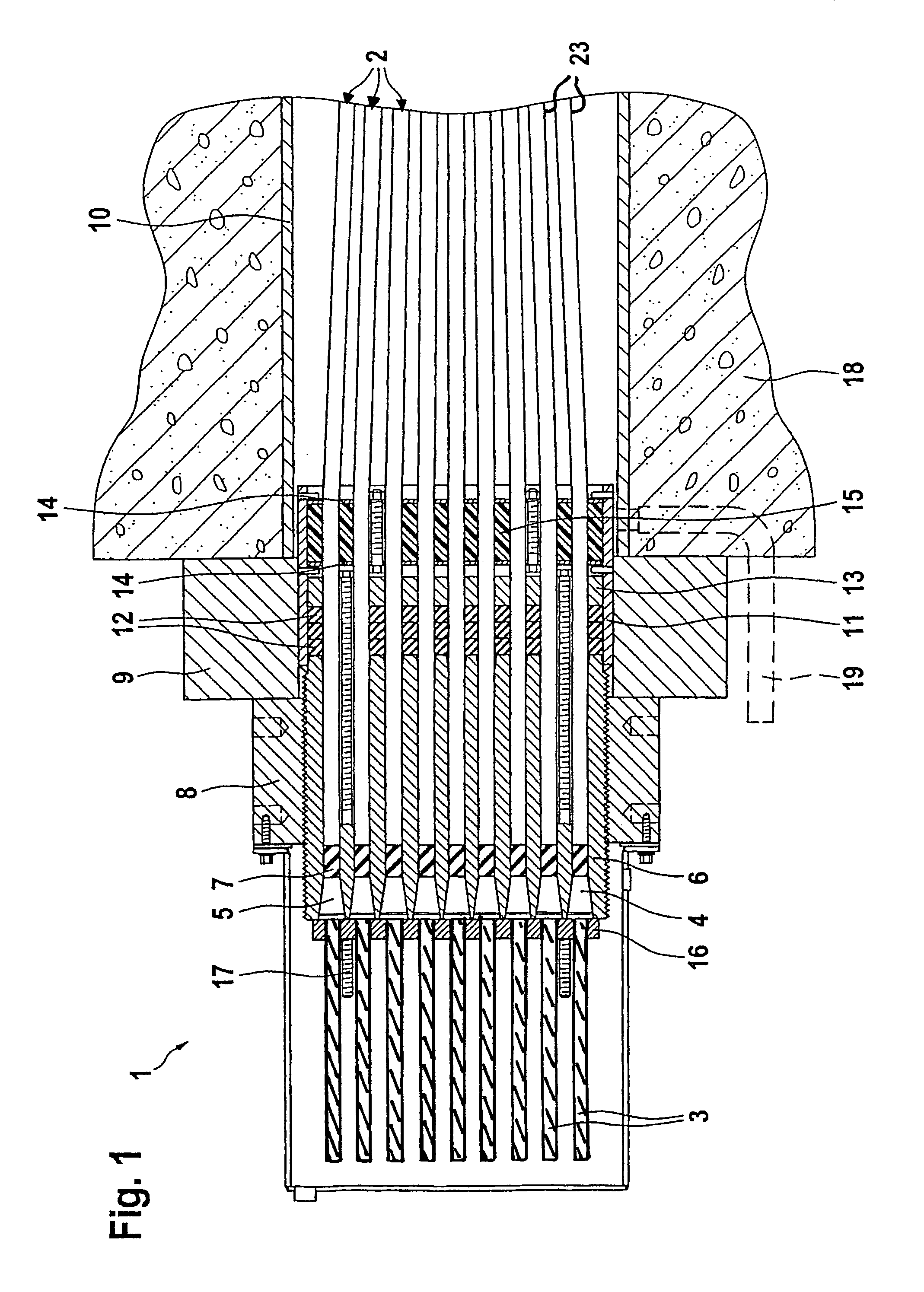
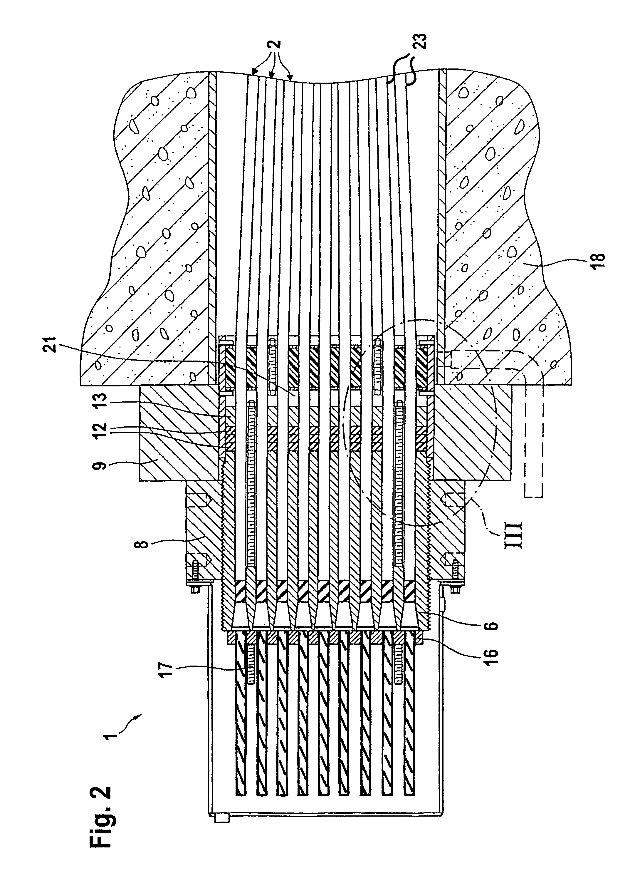
[0018]In FIGS. 1 and 2, the respective anchoring area of a tension member of this invention, for example, an inclined cable for a cable-stayed bridge, is illustrated in two different modes of operation.

[0019]The tension member anchored to an anchoring device 1 of this invention is comprised of a plurality of individual tension elements 2. The tension elements 2, in turn, are comprised of steel wire strands 3, which are provided with corrosion-resistant plastic sheaths 23, for example, protective hoses. The strands 3 are anchored to an anchor body 6, which can be made of steel, by multi-part ring wedges 4 in initially conical, then cylindrical bores 5.

[0020]Next to the ring wedges 4, in the cylindrical area of the bores 5, sockets 7 are arranged, to which the sheaths 23 of the strands 3, which are removed in the anchoring area, abut, and which thus prevent a slipping of the sheaths 23 when the strands 3 are being tightened. The anchor body 6, which is provided with a full-length exte...


PUM


Abstract

An anchoring device for a corrosion-protected tension member includes an anchor body, which is provided with bores for the passage of the tension elements. Sealing discs, which can be compressed by means of a pressure plate and threaded bolts, are provided on a face of the anchor body and lie opposite a downstream face. A perforated disc, which is enclosed by two supporting discs, is located downstream of the sealing discs and the pressure plate. The perforated disc acts as a spacer for the tension elements and is fixed between lugs that are opposite an anchor tube and that is connected to the anchor body. The locking of the perforated disc enables the position of the tension elements to remain parallel, even when the sealing discs are compressed to activate the seal. If individual tension elements have to be replaced, the loosening of the threaded bolts allows the sealing discs to “breathe” and to return to their original position.

Description

[0001]This nonprovisional application claims priority to International Application PCT / EP03 / 03428, which was filed on Apr. 2, 2003, and which claims priority to German Patent Application No. DE 202 05 149.8, which was filed in Germany on Apr. 3, 2002, both of which are herein incorporated by reference.BACKGROUND OF THE INVENTION[0002]1. Field of the Invention[0003]The present invention relates to an anchoring device for a corrosion-resistant tension member, particularly an inclined cable for a cable-stayed bridge having a plurality of tension elements such as steel rods, steel wires, or steel strands, which are arranged inside a tube-shaped sheath. The tension elements are embedded in a corrosion-resistant substance, with each being arranged in a plastic sheath. Each anchoring device has an anchor body, which is provided with bores for the tension elements to pass through. To a side of the anchor body that is opposite from the exposed side, at least one sealing plate is attached, th...

Claims


Application Information

Patent Timeline
Patent Type & Authority Patents(United States)
IPC IPC(8): E04C5/08E01D11/02E01D19/14E04C5/12
CPCE04C5/122E01D19/14
Inventor NUETZEL, OSWALD
Owner DYWIDAG SYST INT GMBH
Why Eureka
Try Eureka