Electrical connector with shield case

a technology of shield case and electric connector, which is applied in the direction of coupling device connection, coupling protective earth/shielding arrangement, electrical apparatus, etc., can solve the problems of excessive force directly applied to the shield case by the mating connector, and the electric device receives a large impact, etc., to achieve sufficient engagement, small range, and wide width

Inactive Publication Date: 2007-02-27
HIROSE ELECTRIC GROUP
View PDF5 Cites 11 Cited by
  • Summary
  • Abstract
  • Description
  • Claims
  • Application Information

AI Technical Summary

Benefits of technology

[0015]According to the present invention, it is preferred that the engaging piece is fitted into the engaging groove in at lease a part of the corresponding range of the engaging groove of the housing. Accordingly, the engaging piece can engage the housing with a strong engaging force, thereby making it possible to prevent the engaging piece from coming off.
[0016]According to the present invention, it is preferred that the engaging piece has a base portion thereof having a width larger than a free end portion thereof. In this case, the engaging groove of the housing has a wide width groove portion having a width larger than the base portion of the engaging piece and a narrow width groove portion having a width smaller than the free end portion of the engaging piece. When the engaging piece is fitted into the engaging groove, the free end portion of the engaging piece is fitted into the narrow width groove portion. With the configuration, the engaging piece has the wide width groove portion having the wide width and strength strong enough to withstand a bending force. Although the narrow width groove portion has a small range, it is possible to obtain sufficient engagement through fitting in.
[0017]Further, according to the present invention, it is preferred that the housing has a stopper portion for abutting against the shield case when the shield case is fitted into a standard position. Accordingly, the shield case is automatically fitted into the standard position with the stopper portion, and it is possible to prevent the shield case from coming off in the fitting direction.
[0018]In the present invention described above, the engaging piece extends from the rear portion of the shield case to be fitted into the housing. After the shield case is attached to the housing, the engaging piece is bend toward the surface of the housing to hold the housing. At the same time, the attaching end portion extends downwardly beyond the bottom surface of the housing from the end portion of the engaging piece, and is directly inserted into the corresponding hole formed in the attaching object member such as the circuit board. Accordingly, the shield case is firmly held with the engaging piece through the circuit board of an electrical device. As a result, when the electrical device with the circuit board mounted thereon is dropped and an external force is applied to the housing, it is possible to prevent the housing from coming off the shield case.

Problems solved by technology

In the connector disclosed in Patent Reference, however, when an electrical device, for example, a mobile phone, with the connector mounted thereon is dropped in a state that a mating connector is connected to the connector, the electrical device receives a large impact, and an excessive force is directly applied to the housing from the mating connector.

Method used


Image

  • Electrical connector with shield case
  • Electrical connector with shield case
  • Electrical connector with shield case

Examples


Embodiment Construction

[0024]Hereunder, embodiments of the present invention will be explained with reference to the accompanying drawings.

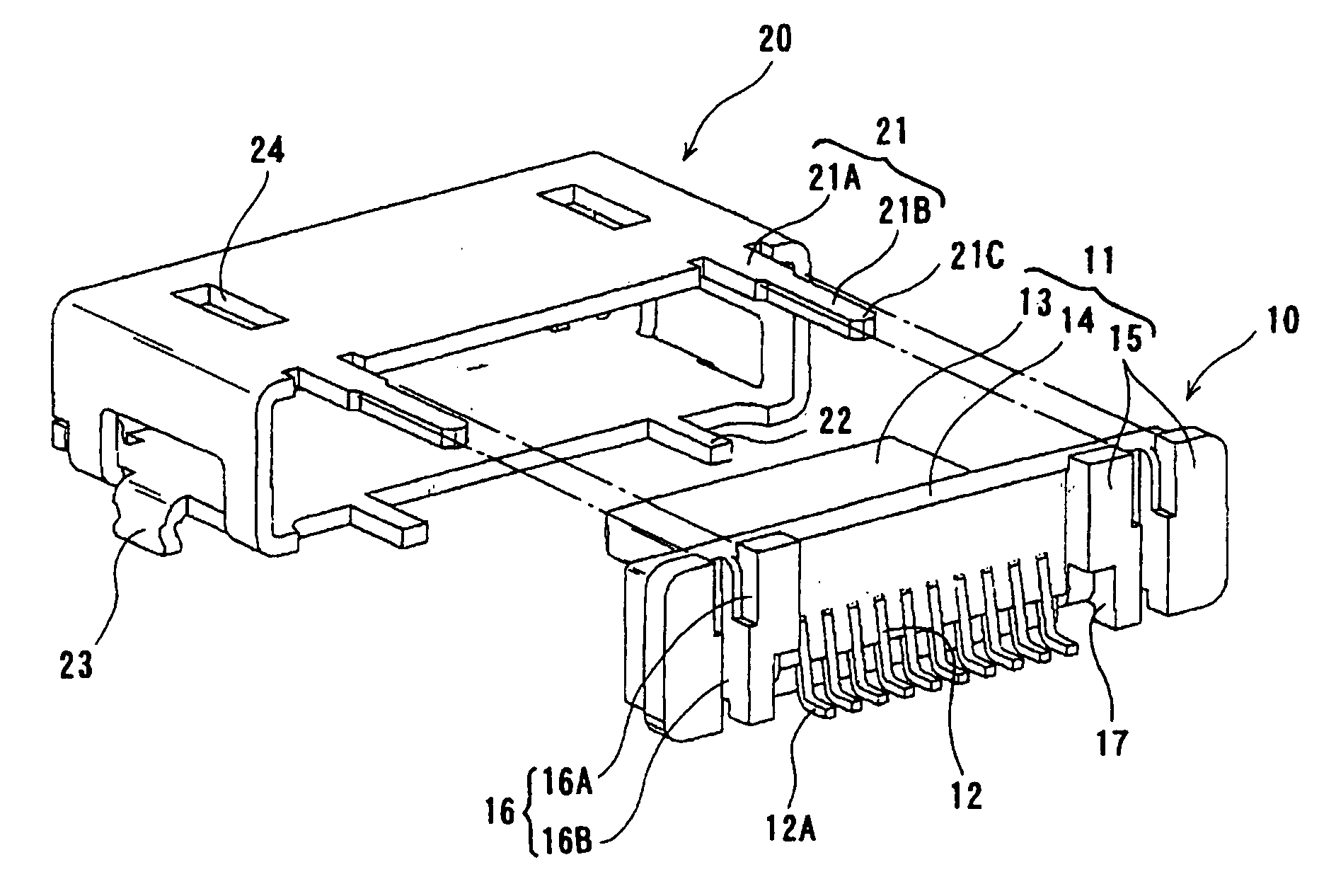
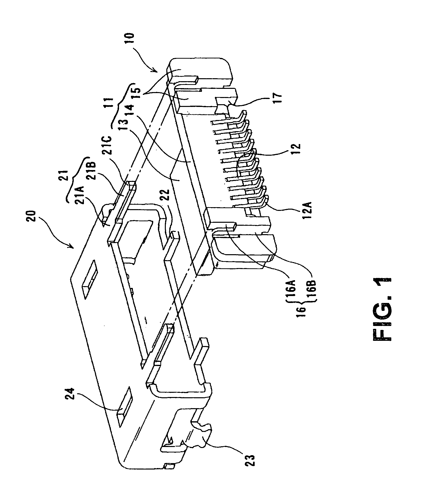
[0025]As shown in FIG. 1, a shield case 20 is to be fitted into a connector main body 10. In the connector main body 10, a plurality of terminals 12 formed of a metal material is disposed in a housing 11 made of an insulating material. The housing 11 includes a fitting portion 13 having a rectangular cylindrical outer surface extending in a forward direction (toward left side in the figure) or a fitting direction relative to a mating connector (not shown); a shield case attaching portion 14 disposed behind the fitting portion 13 and having a rectangular cylindrical outer surface larger than the fitting portion 13; and stopper portions 15 disposed behind the shield case attaching portion 14.

[0026]When the shield case 20 (described in more detail later) is attached to the shield case attaching portion 14 from a front side, a circumference of the fitting portion 13 and th...


PUM


Abstract

In an electrical connector with a shield case, the shield case made of a metal plate is attached to a housing having a front portion to be a fitting side relative to a mating connector. The shield case includes an engaging piece extending from a rear portion of the shield case. The engaging piece of the shield case fitted in is bent toward an outer surface of the housing to engage the housing. In the connector with the shield case, the engaging piece includes an attaching end portion at a portion thereof extending downwardly beyond a bottom surface of the connector after being bent toward the outer surface of the housing. The attaching end portion is inserted into a corresponding hole formed in an attaching object member of the connector for attaching to the attaching object member.

Description

BACKGROUND OF THE INVENTION AND RELATED ART STATEMENT[0001]The present invention relates to an electrical connector with a shield case.[0002]In an electrical connector disclosed in Patent Reference, a shield case is formed through punching a metal plate and bending the same, and is attached to a housing with a terminal disposed therein. In general, such a shield case is provided with an engaging piece for engaging a housing to prevent the shield case from coming off the housing.[0003]As shown in FIG. 5, in the electrical connector disclosed in Patent Reference, a shield case 51 formed of metal with a rectangular cylindrical shape is attached to a housing 53 holding terminals 52. Each of the terminals 52 disposed in the housing 53 includes a connecting portion 52A having an end portion bent at a level of a bottom surface of the housing 53. In a state that the connector is disposed on a circuit board, the connecting portion 52A is connected to a corresponding circuit on the circuit bo...

Claims


Application Information

Patent Timeline
Patent Type & Authority Patents(United States)
IPC IPC(8): H01R13/648
CPCH01R13/6594H01R13/6581
Inventor SHIMOYAMA, MASAO
Owner HIROSE ELECTRIC GROUP
Why Eureka
Try Eureka