Alignment of recovered clock with data signal

a clock signal and data technology, applied in the direction of digital transmission, generating/distributing signals, instruments, etc., can solve the problems of charging pump current mismatch, alignment error, etc., and achieve the effect of small linear rang

Inactive Publication Date: 2006-11-28
ALTERA CORP
View PDF24 Cites 35 Cited by
  • Summary
  • Abstract
  • Description
  • Claims
  • Application Information

AI Technical Summary

Benefits of technology

[0008]The effectiveness of the present invention may be impacted by the type of phase detector used in the aforementioned loop circuit. The ability to change the clock-data alignment is more pronounced in the

Problems solved by technology

In particular, in a clock data recovery application where the clock is recovered using a loop c

Method used


Image

  • Alignment of recovered clock with data signal
  • Alignment of recovered clock with data signal
  • Alignment of recovered clock with data signal

Examples


Embodiment Construction

[0019]As described above, the present invention provides reliable eye centering—i.e., clock-data alignment—by manipulating one of the factors that causes clock-data misalignment. Although the factor is something that one ordinarily would want to eliminate, the fact that it is not the only factor means that manipulating it can cancel out the effect of the other factors. Preferably, the factors that cause clock-data misalignment in a clock data recovery environment are charge pump current mismatch in the loop circuit of the clock data recovery circuitry, process and temperature variations, and clock / data delay variations, and the factor that preferably is manipulated in accordance with the present invention is charge pump current mismatch.

[0020]The invention will now be described with reference to FIGS. 1–5.

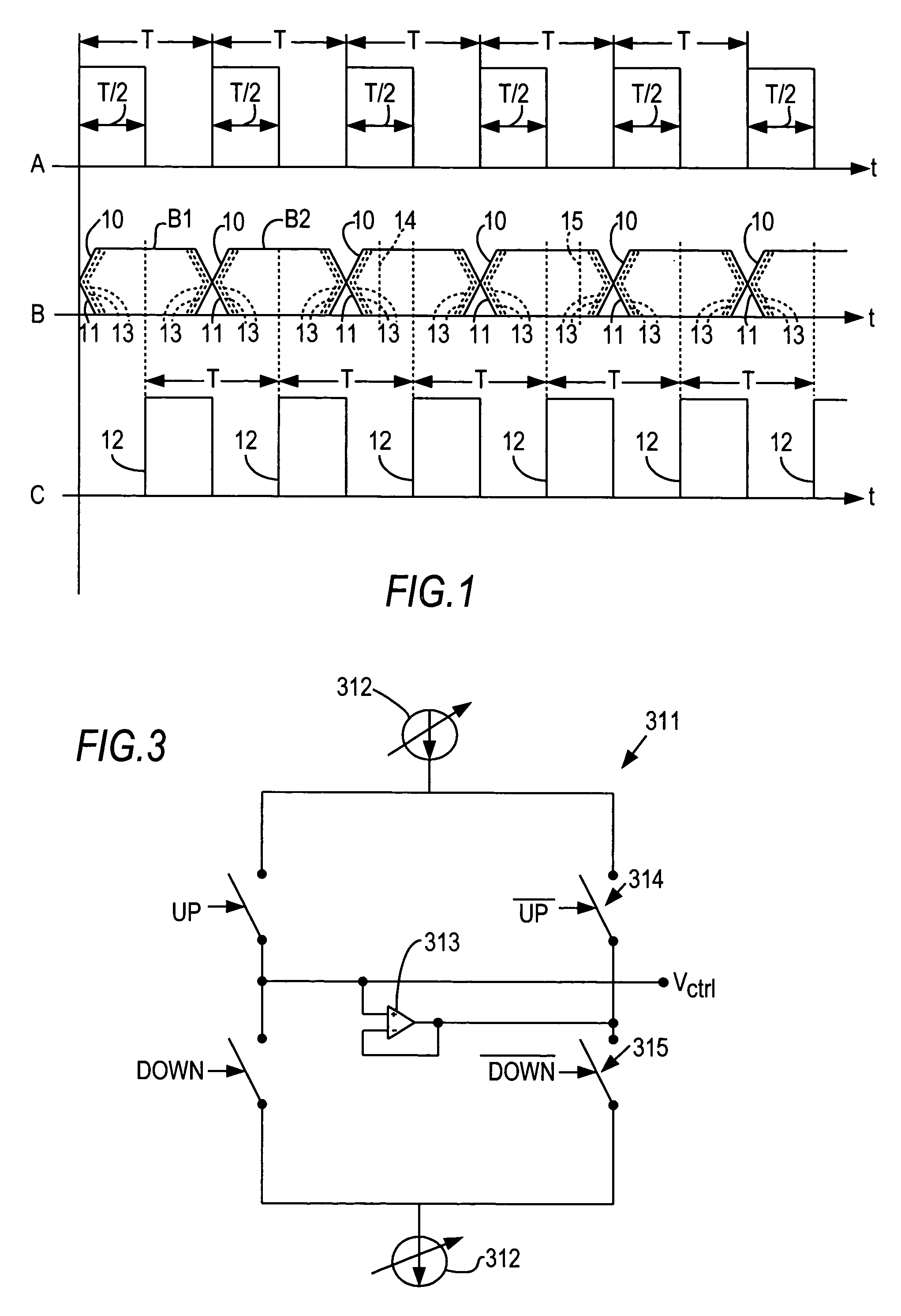
[0021]FIG. 1 shows as waveform A a clock having period T (i.e., a clock rate or frequency of 1 / T). The clock signal preferably includes high intervals each of duration T / 2, separat...


PUM


Abstract

A recovered clock signal is aligned (“eye centered”) with a data signal from which it is recovered by intentionally varying one of the factors or parameters that causes misalignment. For example, if a loop circuit (i.e., a phase-locked loop or a delay-locked loop) is used to recover the clock signal, charge pump current mismatch in the charge pump of the loop circuit is normally one factor in clock-data misalignment, and is also a parameter that can be manipulated. During a test mode, the current mismatch can be varied to obtain the best error rate, which signifies the best clock-data alignment. The test mode can be implemented using built-in self-test circuitry already on the device to transmit test data and then to receive it and analyze it for errors.

Description

BACKGROUND OF THE INVENTION[0001]This invention relates to the alignment of a recovered clock signal with a data signal, commonly referred to as “eye centering.” More particularly, this invention relates to eye centering on a programmable logic device.[0002]It is almost axiomatic that digital systems are clocked. For a clock of period T, the clock signal is typically a series of square (or rectangular) pulses of durations T / 2, separated by zero-amplitude intervals of durations T / 2. Such a clock has a rate or frequency of 1 / T. The clock is used to time data signals, with each data pulse having a duration T. However, there is no reason why consecutive data pulses need be separated by zero-amplitude intervals. Therefore, two or more (n) consecutive data pulses can be transmitted as a single continuous “high” signal of duration nT. In each clock period T, one data pulse can be transmitted. Thus, the data rate of the system is the same as that of the clock rate. In a double data rate sys...

Claims


Application Information

Patent Timeline
IPC IPC(8): G06F11/00
CPCH03L7/0896H03L7/0898H04L7/0004H04L7/033H04L7/043
Inventor WANG, SHOUJUNMEI, HAITAOBEREZA, BILLBAIG, MASHKOORKWASNIEWSKI, TAD
Owner ALTERA CORP
Why Eureka
Try Eureka