Fuel filter arrangement

a technology of fuel filter and vapor separator, which is applied in the direction of filtration separation, machine/engine, separation process, etc., can solve the problems of forming vapor bubbles when discharged into the fuel tank, affecting the efficiency of the fuel pump and the flow rate of fuel delivered to the engine, and the engine is generally unable to utilize all the fuel supplied by the high pressure pump. , to achieve the effect of improving the hot fuel running performance of the pump, improving the running efficiency of the engin

Active Publication Date: 2007-02-27
TI GRP AUTOMOTIVE SYST LLC
View PDF14 Cites 43 Cited by
  • Summary
  • Abstract
  • Description
  • Claims
  • Application Information

AI Technical Summary

Benefits of technology

[0005]Some of the objects, features and advantages that may be included or achieved by one or more embodiments of this invention include improving the running efficiency of an engine of a vehicle, eliminating the flow of fuel vapor to a fuel pump, improving the hot fuel running performance of the pump, increasing the filtration capacity of a fuel filter, increasing the liquid fuel available to the engine, reducing the profile height of a filter arrangement, reducing the number of component parts within a fuel system, improving the efficiency in assembly of a fuel system, providing a filter arrangement of economical design, manufacture and assembly, and providing a filter arrangement having a long life in use.

Problems solved by technology

While in use, the engine is generally unable to utilize all the fuel supplied by the high pressure pump.
The returned fuel generally has been heated, and results in forming vapor bubbles when discharged into the fuel tank.
The presence of vapor bubbles in the fuel tank is undesirable, particularly if the vapor bubbles are drawn into the high pressure fuel pump, which can negatively impact the efficiency of the fuel pump and the flow rate of fuel delivered to the engine.

Method used


Image

  • Fuel filter arrangement
  • Fuel filter arrangement
  • Fuel filter arrangement

Examples


third embodiment

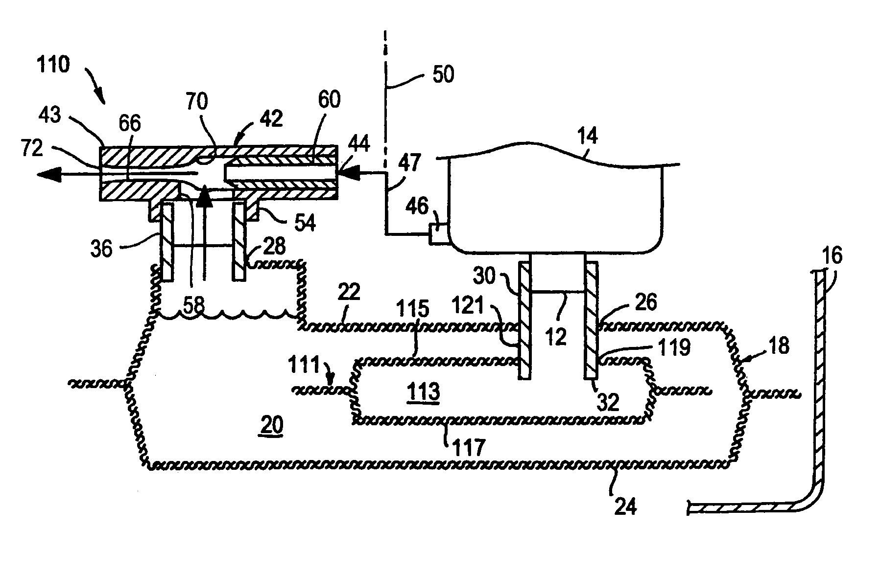
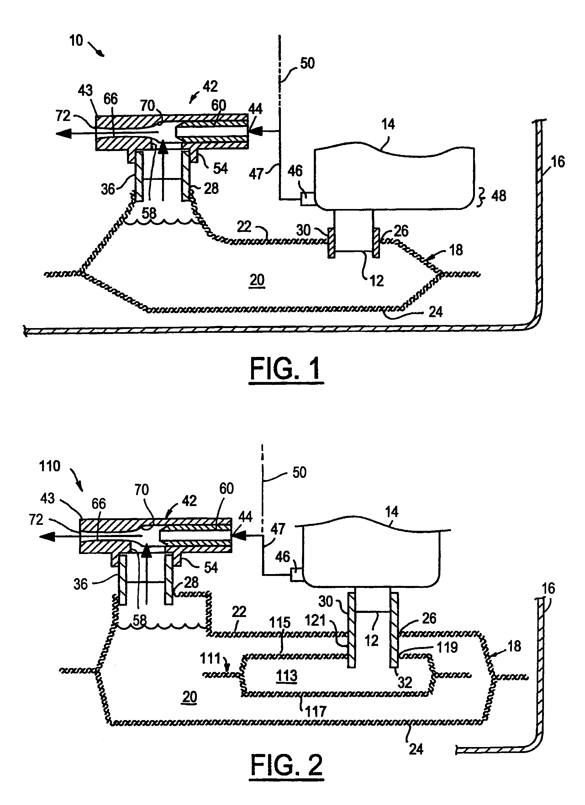
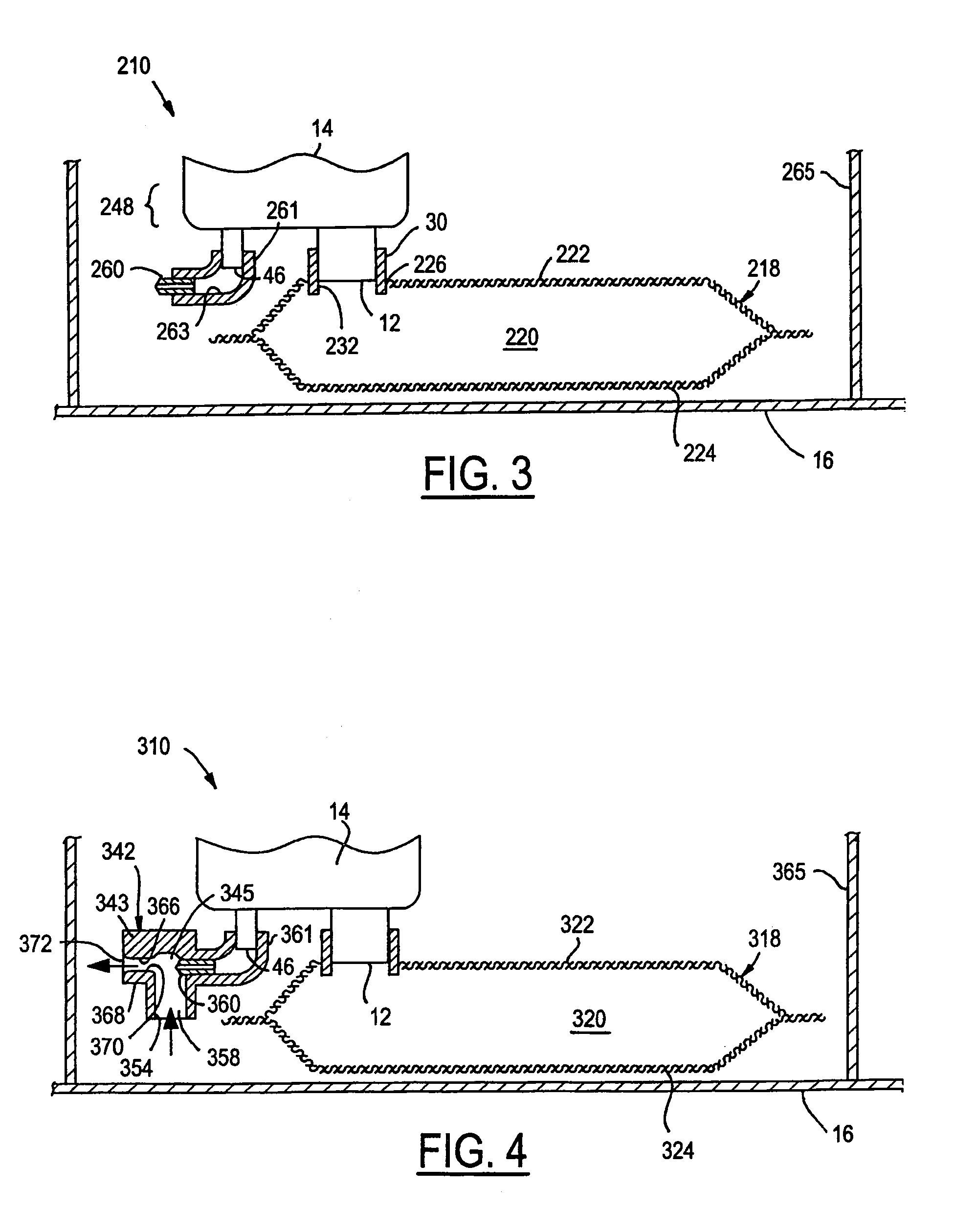
[0030]In FIG. 3, a filter arrangement 210 is shown, wherein the same reference numerals are used to describe like components as in the embodiments above. The filter arrangement 210 has an outer layer 218 of filter material defining a cavity 220 therein. The outer layer 218 has an upper wall 222 and a lower wall 224 with an opening 226 extending through the upper wall 222. The inlet connector 30 extends through the opening 226 to present an inlet 232 generally inside the cavity 220. The outer layer 218 of material is constructed from filter material having the desired porosity, as described above in the previous embodiments, to inhibit fuel vapor bubbles from flowing therethrough and into the cavity 220.

[0031]To further inhibit fuel vapor from entering the cavity 220, the high pressure fuel pump 14 has an outlet 46 arranged to agitate any fuel vapor generally adjacent the inlet 12, thereby causing the fuel vapor to move generally away from the inlet 12. The outlet 46 preferably exten...

fourth embodiment

[0033]In FIG. 4, a fuel filter arrangement 310 is shown, wherein similar reference numerals are used to describe like components as in the embodiments above, however the reference numerals are offset by a factor of 300.

[0034]The fuel filter arrangement 318 has generally the same features as the filter arrangement 218 shown in FIG. 3, and therefore the discussion is limited hereafter to the addition of a jet pump 342 having a venturi 366 downstream from a jet nozzle 360. The jet pump 342 has a body 343 preferably formed as one piece with a tubular extension or elbow 361 extending from the venturi 366 for carrying the jet nozzle 360. Desirably, the elbow 361 is arranged for direct attachment to a high pressure fuel pump outlet 46. The venturi 366 preferably has a necked down or converging inlet 370 in axially spaced alignment downstream from the jet nozzle 360 and a diverging outlet 372. The body 343 has an inlet 354 extending generally laterally therefrom having an opening 358 in flu...

fifth embodiment

[0036]In FIG. 5, a fuel filter arrangement 410 is shown, wherein similar reference numerals are used to describe like components as in the embodiments above, however the reference numerals are offset by a factor of 400.

[0037]The fuel filter arrangement 410 has an outer layer 418 of liquid fuel permeable material defining a cavity 420 having an upper wall 422 and a lower wall 424. The upper wall 422 has a pair of openings 426, 428 and the lower wall 422 has an opening 429. A generally tubular inlet connector 430 is received in one of the openings 426 and attached therein with an adhesive or weld joint, for example. The inlet connector 430 is arranged for operable attachment to an inlet 12 of a high pressure fuel pump 14. A jet pump connector 436 is received in the other opening 428 and attached therein in a generally similar fashion as the inlet connector 430.

[0038]The jet pump connector 436 has a bore 431 sized to receive a jet nozzle 460 therein. The jet nozzle 460 is preferably se...


PUM

PropertyMeasurementUnit
pore sizeaaaaaaaaaa
pore sizeaaaaaaaaaa
permeableaaaaaaaaaa

Abstract

A fuel filter and vapor separator arrangement having at least one layer of liquid fuel permeable material defining at least one substantially enclosed cavity. The permeable material has at least one opening to provide fluid communication of liquid fuel within the cavity with an inlet of a high pressure fuel pump outside the cavity. A jet pump and / or fuel vapor vent is arranged relative to the cavity to facilitate the elimination of fuel vapor flowing to the high pressure fuel pump.

Description

FIELD OF THE INVENTION[0001]This invention relates generally to volatile fuel systems fuel filters, and more particularly to fuel filter and vapor separator arrangement for use with fuel pumps in fuel tanks.BACKGROUND OF THE INVENTION[0002]Fuel tanks in vehicles typically have a high pressure fuel pump within the fuel tank for supplying fuel to an engine of the vehicle. While in use, the engine is generally unable to utilize all the fuel supplied by the high pressure pump. Accordingly, some vehicles have been equipped with a return fuel line to redirect the unused fuel back to the fuel tank for recirculation. The returned fuel generally has been heated, and results in forming vapor bubbles when discharged into the fuel tank. The presence of vapor bubbles in the fuel tank is undesirable, particularly if the vapor bubbles are drawn into the high pressure fuel pump, which can negatively impact the efficiency of the fuel pump and the flow rate of fuel delivered to the engine.[0003]Vario...

Claims


Application Information

Patent Timeline
Patent Type & Authority Patents(United States)
IPC IPC(8): B01D35/027F02M37/22
CPCB01D35/0273F04F5/10F02M37/10F02M37/025B01D2201/208F02M2037/228F02M37/50
Inventor CATLIN, DENNIS J.GETTEL, BRYAN J.KUENZLI, RONALD B.MOSS, GLENN A.ROSS, JOSEPH M.TALASKI, EDWARD J.
Owner TI GRP AUTOMOTIVE SYST LLC
Why Eureka
Try Eureka