Method and device for controlling operation of heat pump unit

a heat pump and operation control technology, applied in the field of operation control methods and operation control units, can solve the problems of high equipment cost, inability to use existing equipment, and high likelihood of high-temperature nhsub>3 /sub>refrigerant gas being brought into contact with the inlet pipe and liquefied, so as to improve cop, enhance the refrigeration effect of the second heat pump unit, and improve the effect of efficiency

Inactive Publication Date: 2013-11-28
MAYEKAWA MFG CO LTD
View PDF6 Cites 8 Cited by
  • Summary
  • Abstract
  • Description
  • Claims
  • Application Information

AI Technical Summary

Benefits of technology

[0034]Note that in the above configuration provided with the second heat pump unit, a condensed refrigerant liquid of the second heat pump unit may be supercooled by the cascade condenser, and the supercooled refrigerant liquid may be caused to return to a low-pressure side refrigerant circulation path of the second heat pump unit. Thus, the refrigeration effect of the second heat pump unit can be enhanced.
[0035]In addition, the cascade condenser may be arranged in parallel with a condenser of the second heat pump unit, and a flow of the refrigerant of the condenser may be regulated to regulate condensing pressure of the condenser. Thus, in the summer, some of the condensing load of the second heat pump unit is born and lightened by the cascade condenser and the condensing temperature of the refrigerant of the condenser of the second heat pump unit is decreased, while the heat source of the cascade condenser is ensured. As a result, it becomes possible to perform a high-efficiency operation with improved COP. In the winter, the condensing load of the second heat pump unit is decreased, and the ratio of the amount of heat to be used as the heat source of the cascade condenser is increased. As a result, it becomes possible to perform the high-efficiency operation of the heat pump unit.
[0036]Accordingly, in a case in which the temperature of the heat-exchanging fluid at the exit of the condenser is variably controlled and operated so as to be increased in the heat pump unit, the condensing load is controlled in parallel with the second heat pump unit. Thus, the temperature of the condensed liquid heat-exchanged with the cascade condenser is increased, which facilitates the high-efficiency operation. With the planned control of these operation conditions in the summer and the winter, the total operation efficiencies of the heat pump unit and the second heat pump unit can be optimized throughout the year. Thus, since the temperature of the heat source corresponding to the initial condensing pressure of the heat pump unit can be ensured, the heat-exchanging fluid can be heated at the initial temperature.
[0037]In the above configuration, the cascade condenser may be arranged in series between the condenser of the second heat pump unit and the compressor, and either a flow of the refrigerant of the condenser may be regulated or condensing pressure of the condenser may be regulated by an outlet pressure regulation valve provided between the cascade condenser and the condenser. Thus, since the sensible heat portion besides the overheat portion of the refrigerant of the second heat pump unit can be effectively used, the heat source of the cascade condenser can be ensured even if the capacity of the second heat pump unit is small. In addition, the condensing pressure of the refrigerant gas of the second heat pump unit is regulated by the outlet pressure regulation valve to decrease the condensing temperature. Thus, the operation efficiency of the second heat pump unit can be improved.
[0038]According to the present invention, there is provided a method for controlling an operation of a...

Problems solved by technology

However, the CO2 refrigerant has higher pressure than general refrigerants at ambient atmospheric temperature and thus cannot be used in existing equipment.
Therefore, equipment supporting the pressure of CO2 is required to be newly constructed besides a pipe system, which gives rise to the problem that an equipment expense becomes high.
Therefore, the pressure of the refrigerant depends on fluctuation factors such as operation conditions and ambient temperature, which gives rise to the problem that the refrigerant-side surface temperature of an inlet pipe, the compressor, and an outlet pipe at the stop and that of the inlet pipe an...

Method used


Image

  • Method and device for controlling operation of heat pump unit
  • Method and device for controlling operation of heat pump unit
  • Method and device for controlling operation of heat pump unit

Examples


second embodiment

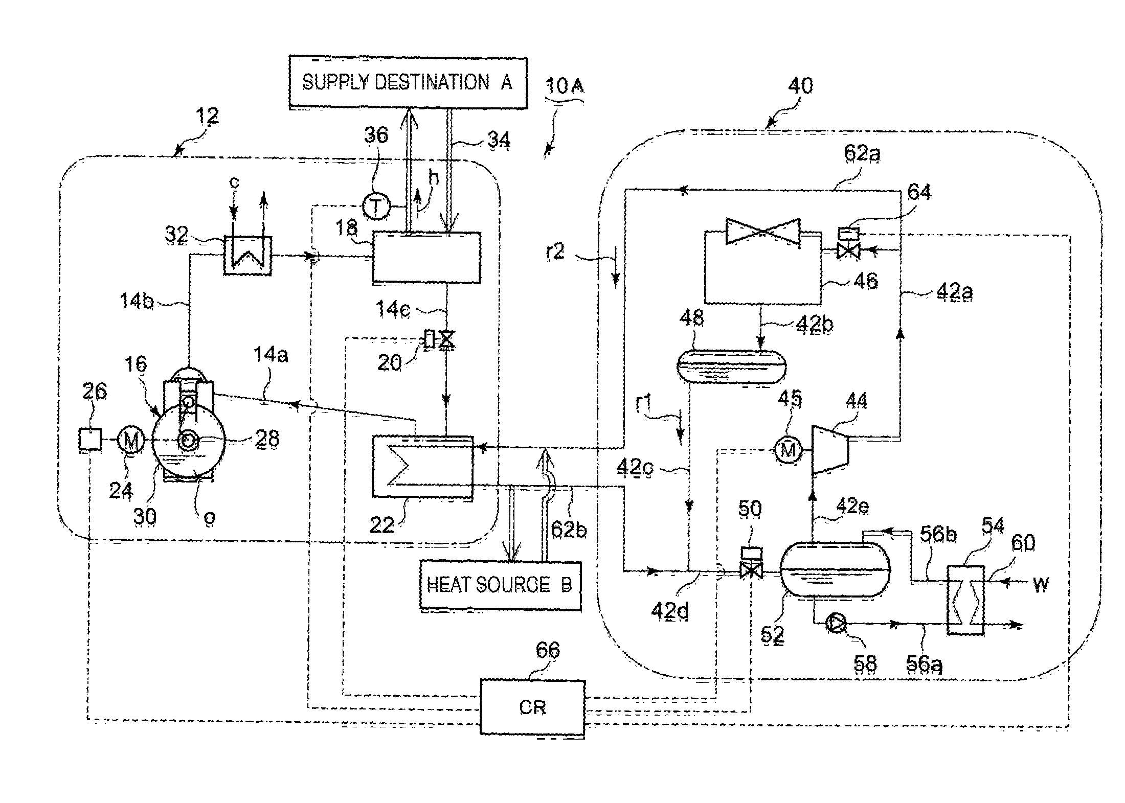
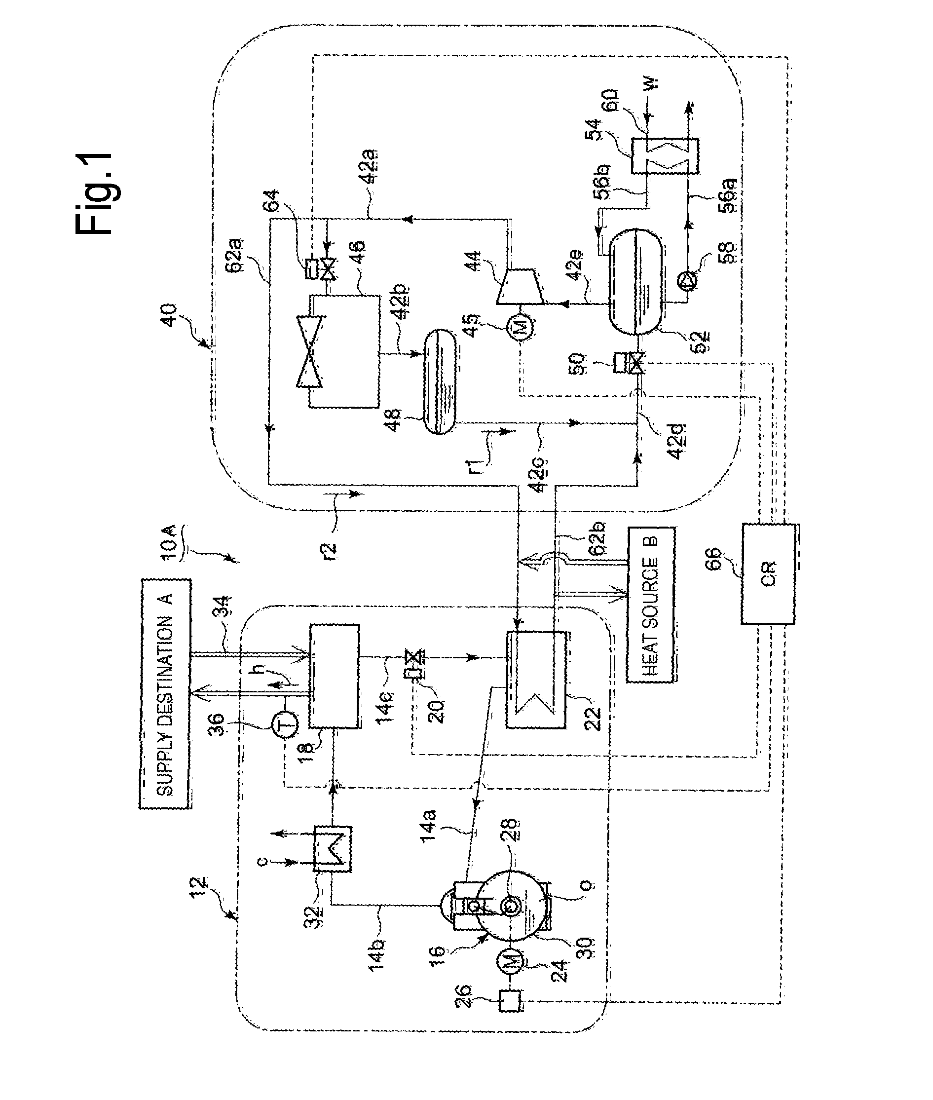
[0087]Next, a description will be given of a second embodiment of the method and the unit of the present invention based on FIG. 8. In a heat pump unit 10B of the embodiment, the outlet refrigerant gas of the compressor 44 is directly introduced into the cascade condenser 22 via the outlet path 42a by the low-pressure side heat pump unit 40. In addition, the branch pipe 62b that returns the heat-exchanged refrigerant from the cascade condenser 22 is connected to the condenser 46. Moreover, the branch pipe 62b is provided with an outlet pressure regulation valve 68 whose opening degree is controlled by the controller 66. That is, the cascade condenser 22 is arranged in series upstream of the condenser 46. Other configurations are the same as those of the first embodiment.

[0088]According to the embodiment, the cascade condenser 22 is arranged in series upstream of the condenser 46. Therefore, even if the capacity of the low-pressure side heat pump unit 40 is small, performance for sup...

third embodiment

[0089]Next, a description will be given of a second embodiment of the method and the unit of the present invention based on FIG. 9. In a heat pump unit 10C of the embodiment, the refrigerant gas outlet from the compressor 44 is condensed by the condenser 46 and then temporarily stored in the receiver 48. The refrigerant liquid r1 stored in the receiver 48 is sent to the cascade condenser 22 via the refrigerant circulation path 42c and used as the heat source of the high-pressure side heat pump unit 12. After being used as the heat source in the cascade condenser 22, the refrigerant liquid r1 is returned to the surge drum 52 via the refrigerant circulation path 42d. Other configurations are the same as those of the first embodiment.

[0090]Besides the function and the effect achieved according to the first embodiment, the embodiment can enhance the refrigeration effect of the low-pressure side heat pump unit 40 in a manner in which the refrigerant liquid r1 is supercooled by the use of...


PUM


Abstract

The temperature of high-temperature water at the exit of a condenser is maintained to be within a setting range by control of, under an operation with all cylinders, capacity of a reciprocating compressor in the period between a maximum allowable load and a minimum load for lubrication, at which the flow of a lubrication oil pump is ensured, based on the revolution-speed control of a drive motor that drives the reciprocating compressor and by control of the capacity of the reciprocating compressor at the minimum load for lubrication or less based on the combination of the control of decreasing the number of operation cylinders and the revolution-speed control of the drive motor. In addition, a heating mechanism is provided on an inlet path of the reciprocating compressor to prevent the liquefied refrigeration flow of a refrigerant liquid to the reciprocating compressor during the operation or at the start.

Description

TECHNICAL FIELD[0001]The present invention relates to an operation control method and an operation control unit that implement the stable supply of high-temperature water or low-temperature water at desired temperature by means of a heat pump unit that uses an NH3 refrigerant.BACKGROUND ART[0002]From the viewpoint of global environmental protection, natural refrigerants having a small ozone depletion potential (ODP) and a small global warming potential (GWP) have been conventionally promoted as operation refrigerants for heat pump units instead of chlorofluorocarbons. Since CO2 serving as a natural refrigerant has a small ODP of 0 and a small GWP of 1, allows high-temperature hot-water supply, and has high COP, it has been practically used in hot-water supply machines for home and business uses.[0003]However, the CO2 refrigerant has higher pressure than general refrigerants at ambient atmospheric temperature and thus cannot be used in existing equipment. Therefore, equipment support...

Claims


Application Information

Patent Timeline
IPC IPC(8): F25B30/02
CPCF25B30/02F25B1/02F25B25/005F25B31/002F25B49/022F25B2339/047F25B2400/074F25B2500/16F25B2600/0253F25B2700/21161F25B2700/21173Y02B30/70
Inventor KUDO, TAKANORIARATA, NORIYUKIUSHIROKAWA, HIROSHIFUKANO, SHUJINAKAJIMA, HISASHI
Owner MAYEKAWA MFG CO LTD
Why Eureka
Try Eureka