Logical data modeling and integrated application framework

a logical data modeling and application framework technology, applied in the field of computer systems, can solve the problems unable to design and maintain large-scale applications, and largely non-automated application development, and achieve the effect of limiting the breadth of claims

Active Publication Date: 2007-02-27
THOMSON REUTERS ENTERPRISE CENT GMBH
View PDF6 Cites 80 Cited by
  • Summary
  • Abstract
  • Description
  • Claims
  • Application Information

AI Technical Summary

Benefits of technology

[0020]The data-modeling framework enables a user to define a logical data model using a series of graphical user interfaces (GUI) or an application-programming interface (API). The logical data model provides functionality that physical databases do not provide. The data-modeling framework dynamically translates the logical data model into a corresponding physical data model. Users utilize the GUI or the API to modify the logical data model, and the system automatically adjusts the physical data model to accommodate the changes to the logical data model. The system shields both the software developer and the software application from complexities and limitations of the physical databases. Furthermore, the developer and the software applications that make use of the data are not limited or restricted to any particular physical data store or physical database.

Problems solved by technology

Despite the importance and popularity of distributed applications, application development has remained a largely non-automated, technical, risk-prone, and costly business process.
This is in part because it is difficult to design and maintain large-scale applications, especially as the data model changes over time.
There are various data modeling tools available to assist developers with the data modeling process, however, these tools are not typically utilized once the data model design is complete.
Physical data models are therefore difficult to change once the database is configured, and especially once the application data has been inserted into the database.
Consequently, in complex systems, compromises are often made to allow the data model to remain unchanged or to change in a way that is easier but not optimal.
This leads to confusion or errors for users not familiar with the original data model design.
Because of the difficulty in creating a well-designed physical data model, and because of the sub-optimal nature of the way data models are changed over time, physical data models often do not properly or intuitively reflect the intended meaning of the data they contain.
Furthermore, physical data models are limited in the concepts that they inherently support.
Also, it can be cumbersome and non-intuitive to navigate a physical data model in order to write the code required to insert and retrieve data from the database.
Applications, like the databases they rely on, are hard to maintain over time.
After changes are made, the application must also be carefully also re-tested, which is a time-consuming process.
Similarly, if the applications change, the underlying database often requires adjustment.
Another area of inefficiency in the application development process is the re-development of common components that occurs because of the difficulty of code re-use.
Therefore, much time and effort is spent redeveloping and implementing features that are common to many applications.
Even within an organization or small development teams, it is difficult to reuse application code because the specific configuration of the physical data model requires that the application code be adjusted as the code is implemented.
But because both applications and physical data models are hard to maintain, data models are often sub-optimal and applications are often left unchanged when the change is needed.
Also, because the application development process interacts with the physical database, the process is complicated, prone to error and inefficient.

Method used


Image

  • Logical data modeling and integrated application framework
  • Logical data modeling and integrated application framework
  • Logical data modeling and integrated application framework

Examples


Embodiment Construction

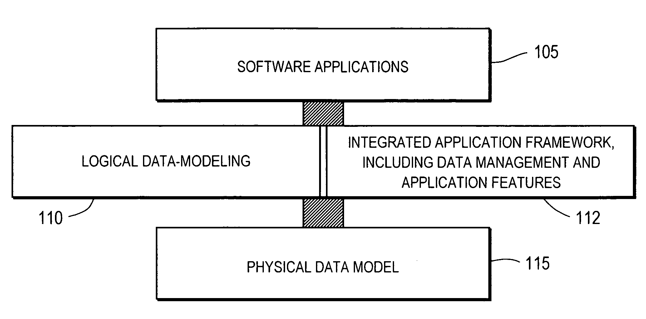
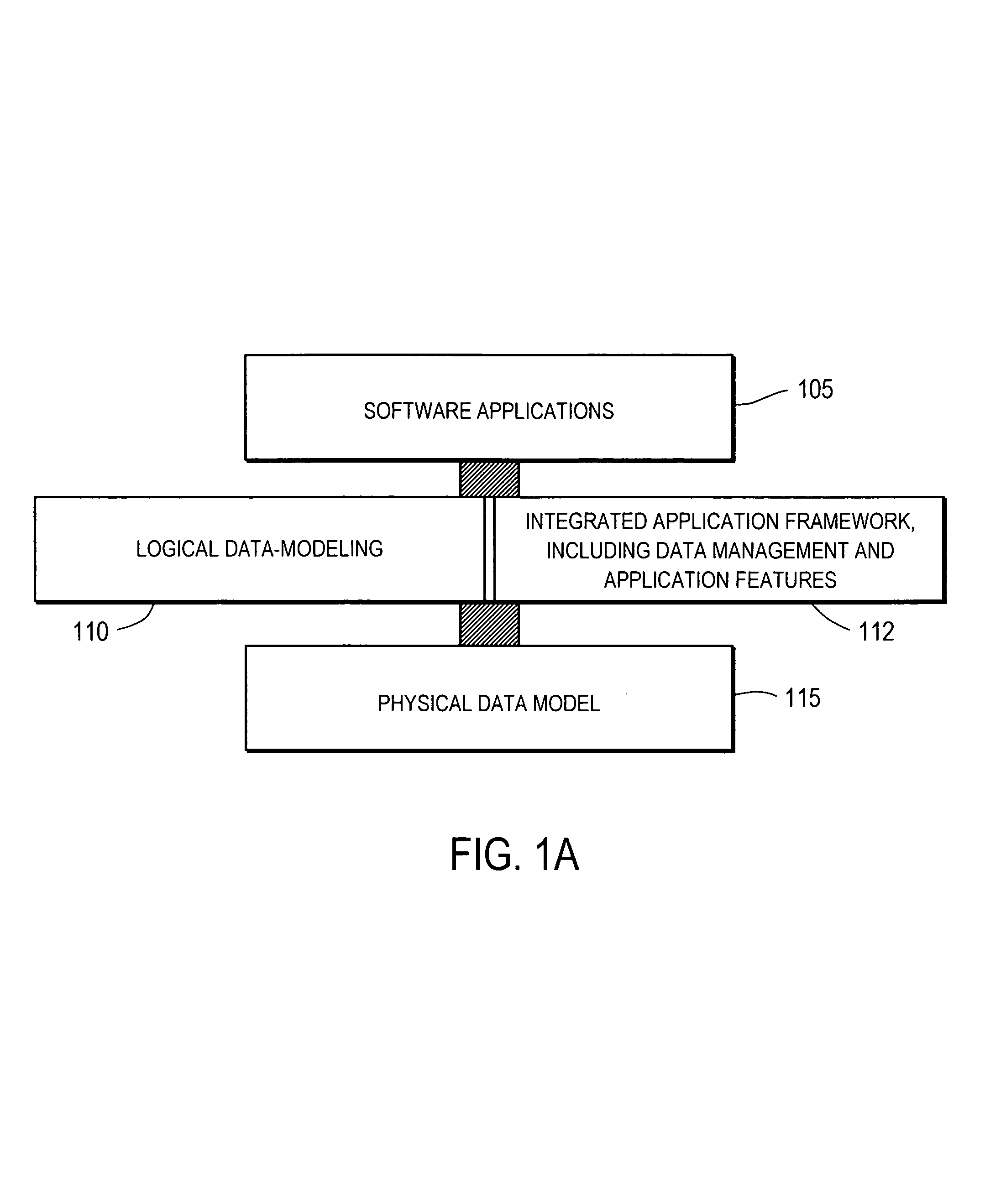
[0066]Described herein is a system for providing application access to a database through a data-modeling and application framework. In one embodiment, a logical data model is defined using a series of graphical user interfaces (GUI) presented by the data-modeling framework. The data-modeling framework dynamically translates the logical data model into a physical data model. The data-modeling and application framework include functionalities that enhance features of the physical data model and dynamically translate changes to the physical data model as changes to the logical data model are made.

[0067]In the following description, for purposes of explanation, numerous specific details are set forth in order to provide a thorough understanding of the present invention. It will be evident, however, to one skilled in the art that the present invention may be practiced without these specific details. In other instances, well-known structures, processes and devices are shown in block diag...


PUM


Abstract

A logical data model is defined using a data-modeling framework. The data-modeling framework enables a user to define the logical data model using a series of graphical user interfaces (GUI) or an application-programming interface (API). The data-modeling framework dynamically translates the logical data model into a corresponding physical data model. The logical data model can be changed using the GUI or API and the physical data model is automatically adjusted to accommodate the changes to the logical data model. The logical data model extends capabilities of the physical data model and automatically allows these capabilities to be available to software developers using an application framework integrated with the data-modeling framework. The application framework enables the developer to configure various application features and data management operations using GUI or API. The application framework is tightly coupled with the data-modeling framework such that changes in the logical data model is automatically reflected in the applications.

Description

RELATED APPLICATION[0001]This application claims priority to a U.S. Provisional Patent Application having Ser. No. 60 / 357293, filed on Feb. 14, 2002 and incorporated herein by reference.COPYRIGHT NOTICE[0002]Contained herein is material that is subject to copyright protection. The copyright owner has no objection to the facsimile reproduction by anyone of the patent document or the patent disclosure, as it appears in the United States Patent and Trademark Office patent file or records, but otherwise reserves all rights to the copyright whatsoever. The following notice applies to the software, screenshots and data as described below and in the drawings hereto: Copyright © 2002, Hubbard One, Inc., All Rights Reserved.FIELD OF THE INVENTION [0003]The present invention relates to a computer system configured to allow software users to structure, access and manage information for use in software applications.BACKGROUND[0004]Since the mid-1990s, web applications have become among the prin...

Claims


Application Information

Patent Timeline
Patent Type & Authority Patents(United States)
IPC IPC(8): G06F9/44
CPCG06F8/34
Inventor FISH, JOHN D.WOLF, BENJAMIN R.GILCHRIST, AMY M.WOLF, MICHAEL D.HARTLEY, DANIEL A.DORN, MATTHEW C.
Owner THOMSON REUTERS ENTERPRISE CENT GMBH
Why Eureka
Try Eureka