
Self-ligating lingual orthodontic bracket

a lingual bracket and orthodontic technology, applied in the field of orthodontics, can solve the problems of less common use of lingual brackets, less understanding of the mechanism of operation to correct improper positioning of teeth and associated oral structures, and many people experience cosmetic, medical, and other problems, so as to reduce or eliminate the problems and disadvantages associated with lingual brackets

Active Publication Date: 2007-03-06
NAVARRO CARLOS F +1
View PDF9 Cites 25 Cited by
  • Summary
  • Abstract
  • Description
  • Claims
  • Application Information

AI Technical Summary

Benefits of technology

"The present invention provides orthodontic brackets that can reduce or eliminate problems and disadvantages associated with previous orthodontic brackets. Specifically, the present invention provides self-ligating lingual brackets that can be used inside a person's mouth and adapted for use with orthodontic wires. The retaining clip of the bracket is designed to secure the orthodontic wire in a self-ligating manner and can apply a resilient force to objects positioned between the clip's first and third portions. The retaining clip can be urged vertically towards the occlusal plane or away from it, depending on the needs of the bracket. The technical effects of the present invention include improved self-ligating capabilities, appropriate orthodontic prescriptions for lingual brackets, and facilitation of access from inside the mouth for inserting, securing, and removing the orthodontic wire."

Problems solved by technology

Many people experience cosmetic, medical, and other problems resulting from improper positioning of the teeth and associated oral structures.
The use of lingual brackets is less common and, accordingly, their mechanism of operation to correct improper positioning of the teeth and associated oral structures is less well understood by most orthodontic professionals.

Method used


Image

  • Self-ligating lingual orthodontic bracket
  • Self-ligating lingual orthodontic bracket
  • Self-ligating lingual orthodontic bracket

Examples


Embodiment Construction

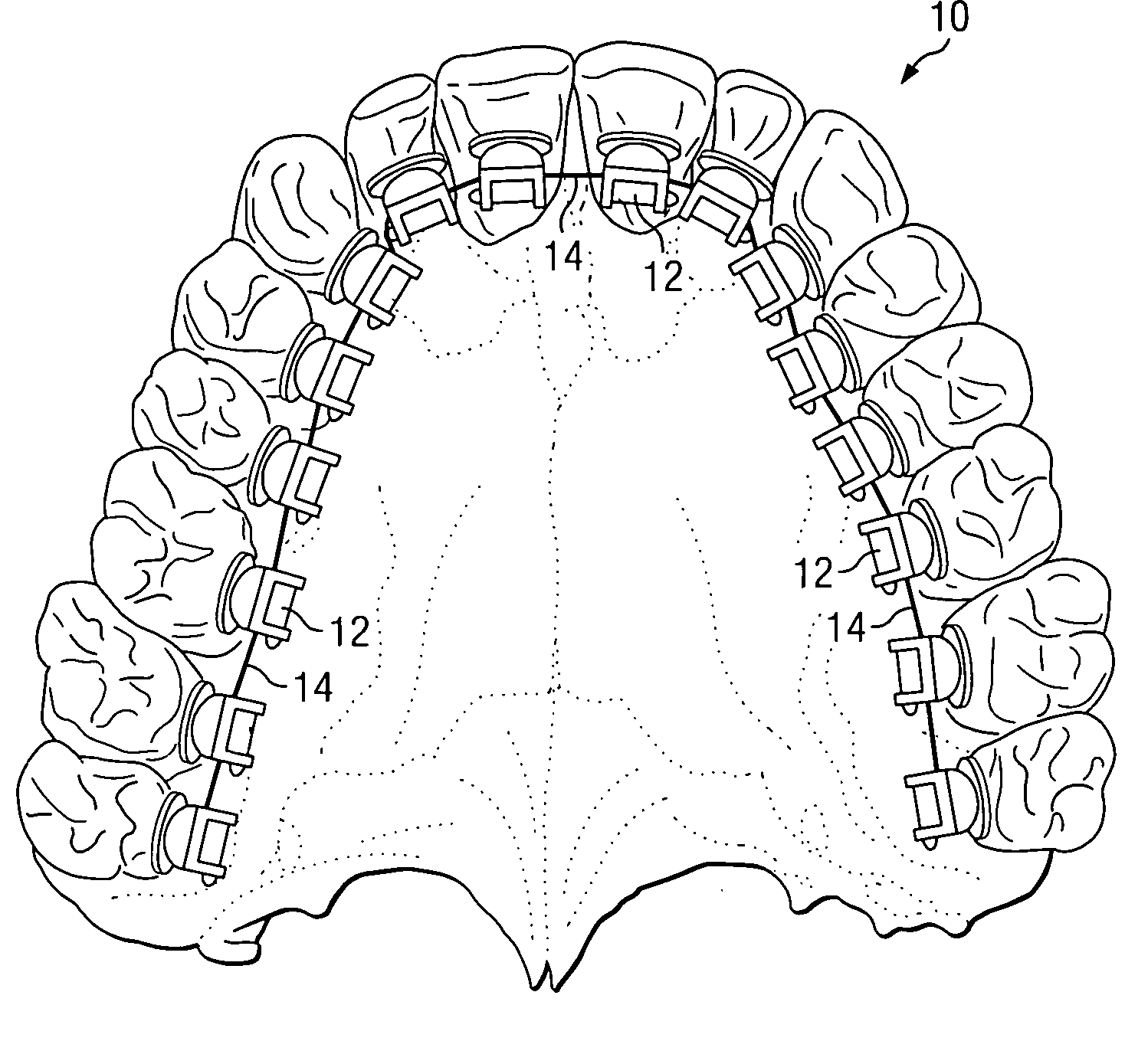
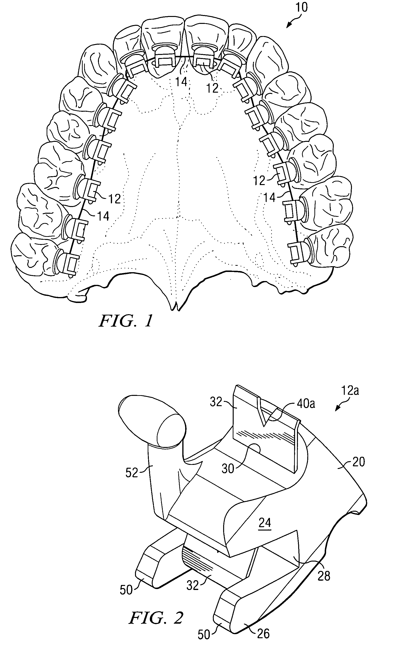
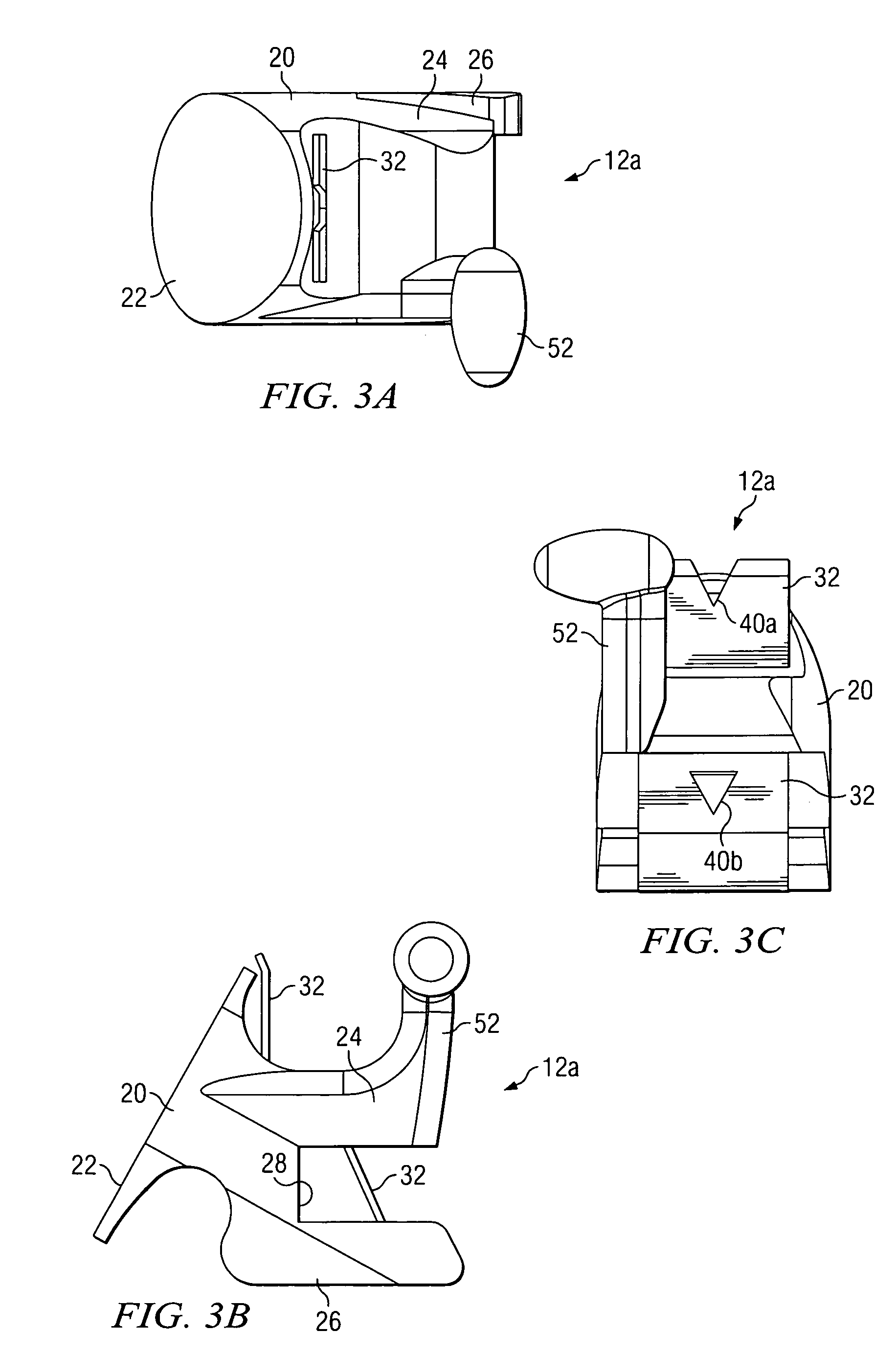
[0026]FIG. 1 illustrates a bottom view of a person's upper arch 10 with example self-ligating lingual orthodontic brackets 12 affixed to the upper teeth. For example, brackets 12 may be affixed to the upper teeth using a conventional indirect bonding technique or in any other suitable manner. Although upper arch 10 is illustrated with substantially identical brackets 12 affixed to all of the upper teeth, brackets 12 may be affixed to any two or more of the upper teeth, brackets 12 may be affixed to any two or more of lower teeth instead or in addition to two or more of the upper teeth, and a bracket 12 affixed to a tooth may be the same as or different than a bracket 12 affixed to another tooth in configuration, size, or both. As one example, brackets 12 affixed to central teeth may be different in both configuration and size than brackets 12 affixed to cuspids, bicuspids, or molars. As another example, a bracket 12 affixed to an upper tooth may be larger than a bracket 12 affixed t...


PUM


Abstract

According to one embodiment, a self-ligating lingual orthodontic bracket includes a base, flanges extending from the base to define a slot, and a clip. The clip applies a force to an object to secure the wire within the slot in a self-ligating manner. The clip is adapted to be urged vertically toward the occlusal plane from a closed position to an open position to expose the slot to receive the wire, the clip being biased against the second flange when the clip is in the open position due to the applied force. The clip is adapted to be urged vertically away from the occlusal plane from the open position to the closed position to secure the wire within the slot, the clip being biased against the wire when the clip is in the closed position and the wire is secured within the slot due to the applied force.

Description

TECHNICAL FIELD[0001]This invention relates generally to orthodontics and in particular to a self-ligating lingual orthodontic bracket.BACKGROUND[0002]Many people experience cosmetic, medical, and other problems resulting from improper positioning of the teeth and associated oral structures. Through the use of orthodontic brackets affixed to the teeth and coupled to one another with orthodontic wire, the teeth may be forced into proper position over an extended period of time. Labial orthodontic brackets are affixed to the labial or outside surface of the teeth. The use of labial brackets is common and their mechanism of operation to correct improper positioning of the teeth and associated oral structures is well understood by most orthodontic professionals. Certain previous labial brackets are self-ligating, meaning that a bracket includes a clip or other mechanism to secure the orthodontic wire in place against the lingual surface of the bracket. In contrast to labial brackets, li...

Claims


Application Information

Patent Timeline
Patent Type & Authority Patents(United States)
IPC IPC(8): A61C7/12A61C3/00A61C7/28
CPCA61C7/287
Inventor NAVARRO, CARLOS F.NAVARRO, MARCO A.
Owner NAVARRO CARLOS F
Learn More