Coaxial cable connector

a technology of coaxial cable and connector, which is applied in the direction of coupling contact members, coupling device connections, two-part coupling devices, etc., can solve the problems of deformation of the fitting retaining force of the connector, instantaneous interruption, and plastic deformation of the receptacle fitting portion or looseness in the crimped portion, so as to improve the elastic force, increase the elastic force, and reduce the displacement and deformation of the same portions

Inactive Publication Date: 2007-03-06
HOSIDEN CORP
View PDF6 Cites 15 Cited by
  • Summary
  • Abstract
  • Description
  • Claims
  • Application Information

AI Technical Summary

Benefits of technology

[0009]Therefore, it is a main object of the present invention to prevent the receptacle fitting portion of a coaxial cable connector and, particularly a small-height and small-size coaxial cable connector, from degrading its fitting retaining force due to repeated fitting to a receptacle, resulting in occurrences of inconvenience such as accidental disengagement.
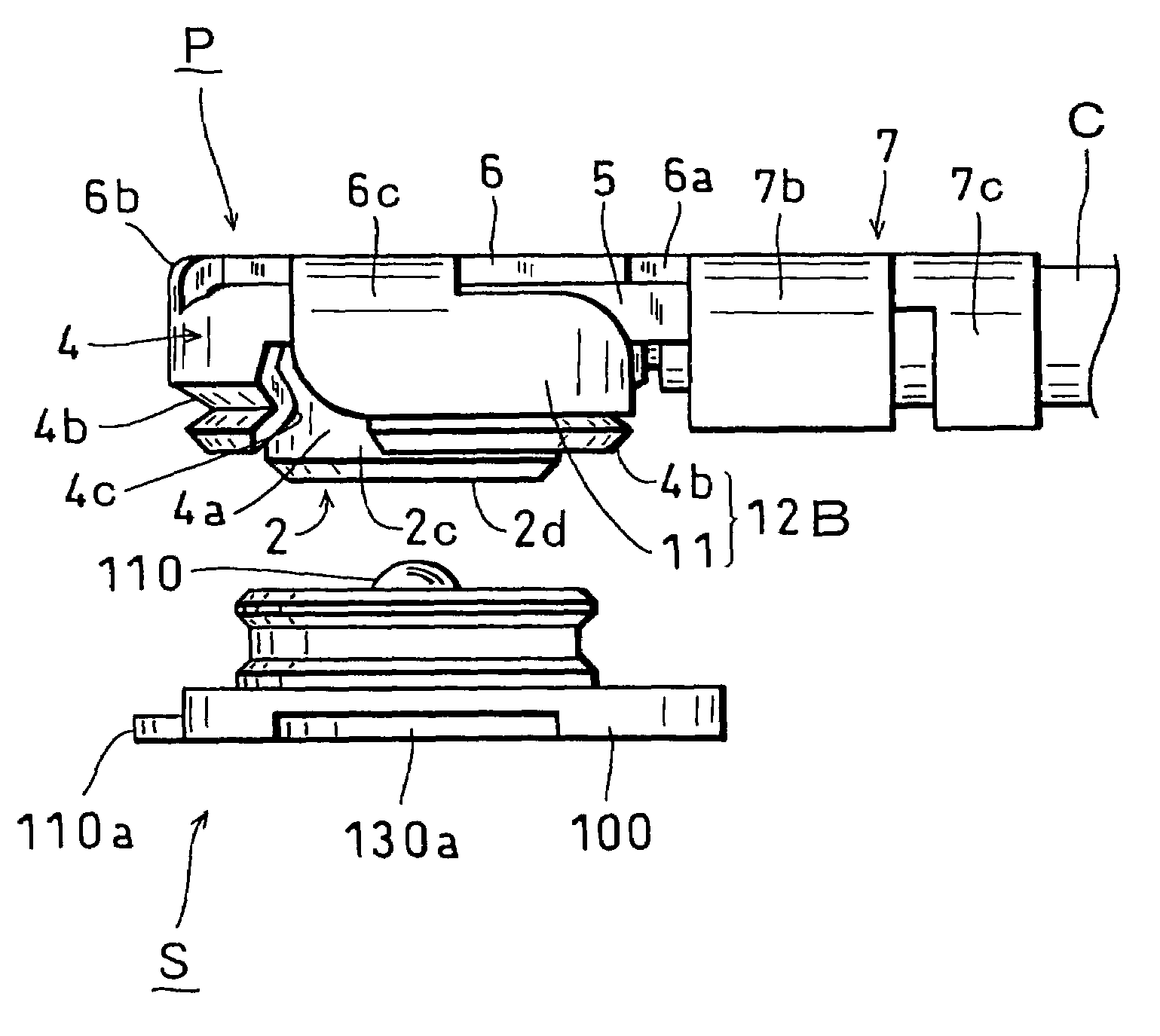
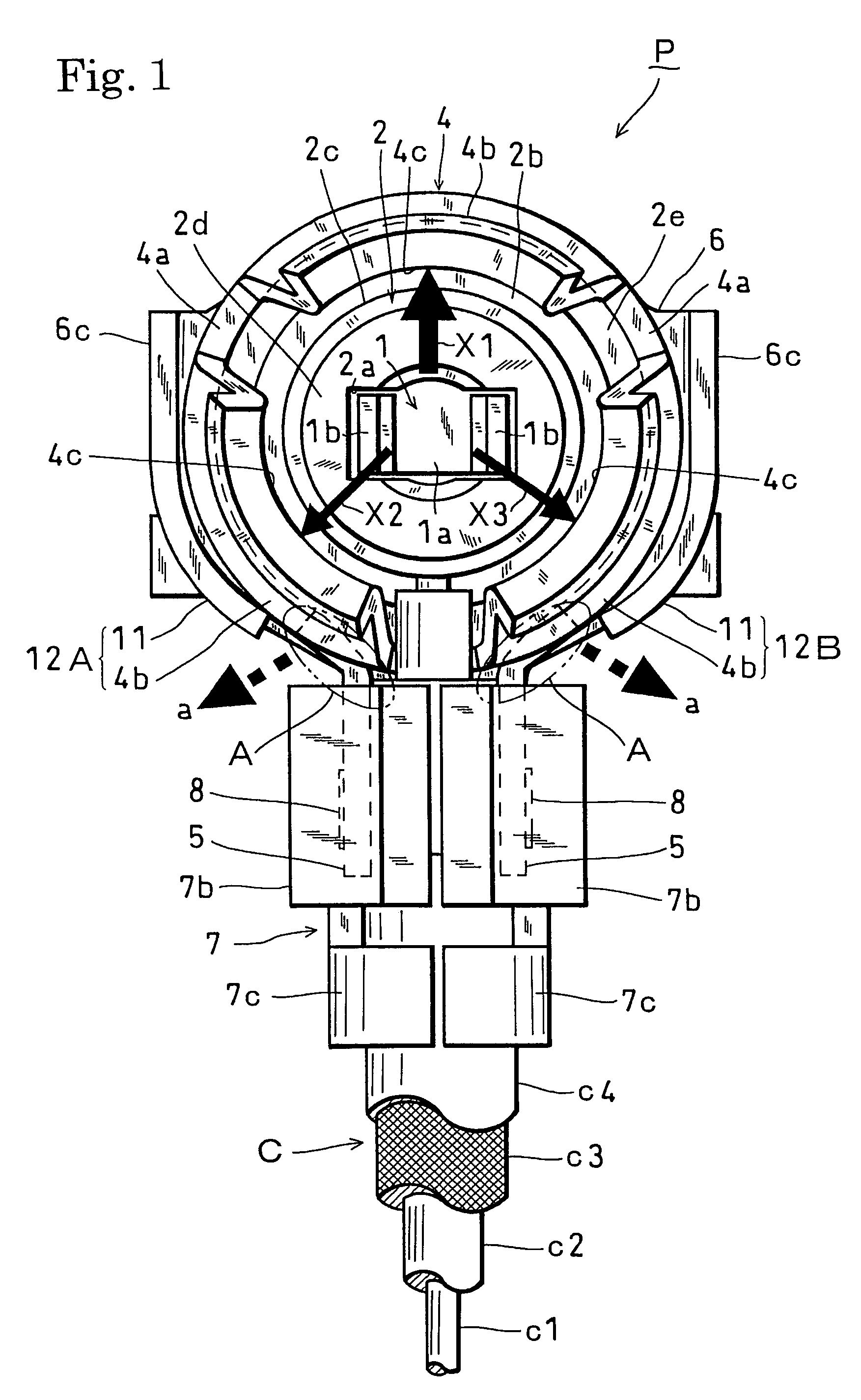
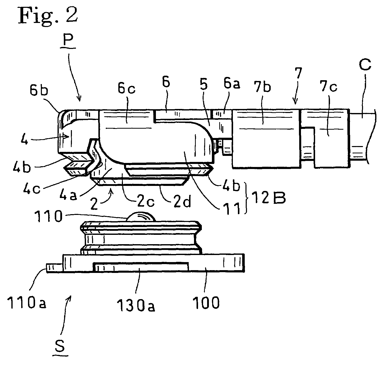
[0014]In the case of a coaxial cable connector including a contact which is connected to a central conductor of a coaxial cable, an insulation body internally equipped with said contact, and a cylindrical receptacle fitting portion including a plurality of arc-shaped elastic springs which are arranged outside said insulation body on a concentric circle and are connected to an outer conductor of said coaxial cable, when the connector is pulled out from the receptacle by pulling the coaxial cable, a largest stress is exerted on the cable drawing-out portion of the receptacle fitting portion (the A and B portions in FIG. 1), which forces the portions outwardly (the directions of the arrows a and b in FIG. 1) to expand them. However, in the present invention, since the receptacle fitting portion partially has the configurations of the double springs, it has an increased elastic force which disperses stresses therein to alleviate displacement and deformation of the same portions. Since the receptacle fitting portion has an increased elastic force and thus is less prone to deformation, it is possible to effectively prevent degradation of the fitting retaining force due to repeated insertion and pull and also it is possible to increase the initial retaining force, which improves the reliability of the fitting and contact. This can prevent the receptacle fitting portion from degrading its fitting retaining force resulting in inconvenience of accidental disengagement, etc., due to repeated fitting of a coaxial cable connector, particularly a small-height and small size L-shaped coaxial cable connector, into a receptacle.
[0015]The receptacle fitting portion has a lowest strength at the cable drawing-out portion (the A and B portions in FIG. 1). Therefore, by forming the adjacent arc-shaped elastic springs sandwiching the coaxial cable drawn out outwardly in the radial direction from the receptacle fitting portion to have the double-spring configuration, the lowest-strength portion of the receptacle fitting portion can be reinforced, thereby effectively alleviating degradation in the fitting retaining force due to repeated insertion and pull.
[0016]The outer elastic springs of the double springs are bent into an arc shape or a tangential straight shape such that their movable tip end portions are more inward than the outer diameter of the receptacle fitting portion, before being placed outside the receptacle fitting portion. Consequently, when the outer elastic springs of the double springs are placed outside the receptacle fitting portion, an initial displacement is generated, thus exerting a load to the double springs. Since the receptacle fitting portion has already had an increased elastic force before the coaxial cable is pulled at the state where the connector is fitted to the receptacle, it has greater resistance against deformation and exhibits reduced characteristic changes against repeated insertion and pull, in comparison with configurations which constitute double springs halfway through the displacement. Consequently, it is possible to effectively alleviate degradation of the fitting retaining force due to repeated insertion and pull. Also, the bending of the outer elastic springs of the double springs can be performed after they are placed outside the receptacle fitting portion, and in such a case, their movable tip end portions are bent into an arc shape or a tangential straight shape such that they are brought into contact with the outer peripheral surface of the receptacle fitting portion. In the case of bending the outer elastic springs of the double springs after placing them outside the receptacle fitting portion, the assembly of the connector will be easier.
[0017]Further, since the outer elastic springs of the double springs are formed, by bending, from portions of the outer conductor shell placed outside the receptacle fitting portion, the outer elastic springs are integral with the outer conductor shell, which can alleviate reduction of the fitting retaining force due to repeated insertion and pull without increasing the number of components and the number of assembly processes. In addition to forming the outer elastic springs of the double springs integrally with the outer conductor shell, they can also be constituted by U-shaped springs made from metal sheets or made by wire-forming or can be also constituted by resin springs formed concentrically with the body cylindrical shape by forming integrally with the insulation body.

Problems solved by technology

However, due to the small heights and small sizes, they are pulled out by pulling the coaxial cable in many cases.
In such cases, though the connector is easily disengaged through the principle of leverage as a bottle opener, stresses are concentrated to portions having poor construction strength in the receptacle fitting portion at this time, resulting in plastic deformation of the receptacle fitting portion or looseness in the crimped portion.
If such insertion and pull are repeated, this may significantly degrade the fitting retaining force of the connector to cause accidental disengagement or vibrations, resulting in instantaneous interruption.
Furthermore, with decreasing height and size, the designing of springs in the receptacle fitting portion becomes more difficult making it more difficult to ensure required initial retaining force, which induces the problem of degradation of the fitting retaining force of the connector.

Method used


Image

  • Coaxial cable connector
  • Coaxial cable connector
  • Coaxial cable connector

Examples


Embodiment Construction

[0025]Hereinafter, embodiments of the present invention will be described, on the basis of the drawings. In the figures, S designates a connecter receptacle for a coaxial cable and P designates a connector (plug) for a coaxial cable. The receptacle S is constituted by a resin insulation body 100 having a rectangular-plate shape, a shaft-type metal (conductive) contact 110 vertically extending from substantially the center potion of the upper surface of the insulation body 100, and a cylindrical metal (conductive) outer conductor 130 extending vertically from the upper surface of the insulation body 100 around the contact 110 with an annular space 120 interposed therebetween, wherein the insulation body 100 is concentric with the contact 110. Further, the receptacle S includes, at the base end portion of the contact 110, a substrate contact portion 110a having an lower surface exposed flash with the bottom surface of the insulation body 100 and a tip end portion protruded from the ce...


PUM


Abstract

A coaxial cable connector including a contact connected to a central conductor of a coaxial cable, an insulation body internally equipped with the contact, and a cylindrical receptacle fitting portion including a plurality of arc-shaped elastic springs which are arranged outside the insulation body on a concentric circle and connected to an outer conductor of the coaxial cable. In order to overcome the problem of degradation of the fitting retaining force of the receptacle fitting portion due to repeated fitting to a receptacle, there are provided elastic springs placed outside the receptacle fitting portion for making the receptacle fitting portion to partially have the configuration of double springs. Especially, the configuration of the double springs is formed by adjacent two arc-shaped elastic springs sandwiching the coaxial cable drawn out outwardly in the radial direction from the receptacle fitting portion.

Description

BACKGROUND OF THE INVENTION[0001]1. Field of the Invention[0002]The present invention relates to a coaxial cable connector for use in a compact electronic apparatus such as a communication apparatus such as a portable phone or an electric measurement apparatus, among coaxial cable connectors for use in connections between substrates of various types of electronic apparatuses and coaxial cables and, more particularly, to a coaxial cable connector plug which is mounted to an end portion of a coaxial cable and is fitted to a coaxial cable connector receptacle mounted on a substrate.[0003]2. Description of the Prior Art[0004]To cope with the trend toward thinner, lighter and higher-density compact electronic apparatuses, there have been small-height and small size coaxial cable connectors (plugs) having reduced receptacle-fitting heights and reduced receptacle-mounted areas. Such connectors are known as L-shaped coaxial cable connecters which are fitted to an receptacle in the direction...

Claims


Application Information

Patent Timeline
Patent Type & Authority Patents(United States)
IPC IPC(8): H01R9/05H01R13/18
CPCH01R13/18H01R24/50H01R2103/00
Inventor NAGATA, TAKAYUKINAKAI, YASUO
Owner HOSIDEN CORP
Why Eureka
Try Eureka