
Product configuration using configuration patterns

a product configuration and configuration pattern technology, applied in the field of computer-based product configuration, can solve the problems of affecting the use of components, and affecting the product configuration

Active Publication Date: 2007-03-06
VERSATA DEV GROUP
View PDF25 Cites 143 Cited by
  • Summary
  • Abstract
  • Description
  • Claims
  • Application Information

AI Technical Summary

Problems solved by technology

As product specifications become more customized and varied, configuration alternatives increase and the task of configuring a product becomes more complex.
In general terms, a constraint-based system places constraints on the use of a component in a configuration.
For example, a hard disk drive cannot be added to the configuration unless a compatible storage device controller is available for use by a requested storage device.
While the configuration modeling software can address configurations for complex products, the configuration modeling software itself is generally very complex and requires a high level of skill and effort to maintain and to create new product configurations.
In addition, even simple modifications to the configuration modeling software may require significant time and effort to implement, leading to significant cost and expense.
Thus, creating systems for configuration of complex products such as telecommunications systems is a complex task for the following reasons:1. The problem itself is difficult given the enormous number of combinations to be considered when searching through the space of configurable solutions; and2. Creating a representation of the product (classes, components and configuration logic) that is easy to maintain and extend is very difficult, often requiring advanced programming skill and deep domain knowledge.
One of the difficulties and significant source of expense in modeling a product results from the fact that it is rare that one individual possesses the knowledge required for tasks 1–5.

Method used


Image

  • Product configuration using configuration patterns
  • Product configuration using configuration patterns
  • Product configuration using configuration patterns

Examples


example

[0183]FIG. 8 illustrates the ConfigureOpticalInterfaceCard pattern 802. The ConfigureOpticalInterfaceCard pattern 802 is used to instantiate one or more optical interface cards 801, based on the type of optical interface (OC-3, OC-12, OC-48, etc) required. The ConfigureOpticalInterfaceCard pattern 802 could be used to, for example, satisfy the requirements of an optical tributary or a high-speed interface.

[0184]The characteristics of the required optical interface card 801 are specified by the attributes in the OpticalInterfaceCardRequirement 804 component, as shown in the diagram. Specifically, optical interface cards may be described by the following:[0185]Card type—the type of optical interface card required, specified by the card_required_CL 815 attribute on the OpticalInterfaceCardRequirement 804 component.[0186]Number of ports required—the number of ports required from the optical interface card, specified by the ports_required_F attribute on the OpticalInterfaceCardRequiremen...


PUM


Abstract

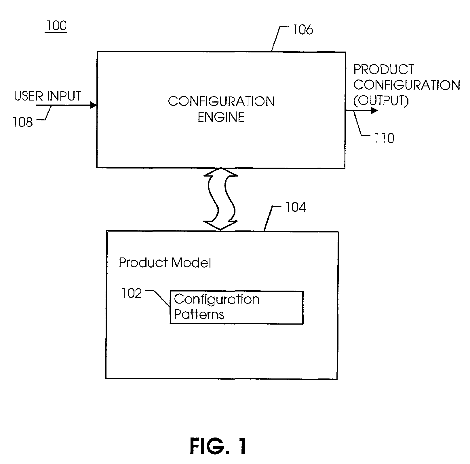
In a particular embodiment, configuration patterns are used to provide solutions to configuration problems that repetitively occur. Use of configuration patterns in connection with a configuration model has many benefits. A configuration patterns is a parameterized or otherwise easily extensible solution to that problem, such that the solution is reusable by modifying the parameters of the pattern or extending the pattern in pre-defined ways. Configuration patterns are inherently data-driven and provide improved maintenance for data and logic as well as reduced programming effort. Configuration patterns can be reused within and across different product families and can be specialized from other patterns. Thus, the use of configuration patterns facilitates reduced maintenance cost and reduced programming effort for product configuration data and logic systems.

Description

CROSS-REFERENCE TO RELATED APPLICATION(S)[0001]This application claims the benefit of U.S. Provisional Application No. 60 / 343,670, filed Dec. 28, 2001 and entitled “Product Configuration Using Configuration Patterns”.[0002]This application claims the benefit of U.S. Provisional Application No. 60 / 343,666, filed Dec. 28, 2001 and entitled “Telecommunications Configuration Model for Product Configuration”.[0003]This application relates to “Telecommunications Configuration Model for Product Configuration”, application Ser. No. 10 / 085,995, with common assignee and filed on Feb. 28, 2002.BACKGROUND[0004]1. Field of the Invention[0005]The present invention relates generally to the field of computer-based product configuration.[0006]2. Background Description[0007]Configuring a product refers to the process of selecting, constructing, and connecting components to satisfy a particular need or request. Configuring a product has been described, for example, in U.S. Pat. No. 5,515,524 entitled ...

Claims


Application Information

Patent Timeline
Patent Type & Authority Patents(United States)
IPC IPC(8): G06F9/44
CPCG06F8/10
Inventor DARR, TIMOTHY P.BEAUMONT, RAYMOND L.SHARMA, NIRAD P.
Owner VERSATA DEV GROUP
Learn More