Self-locking support arm

a self-locking, support arm technology, applied in the field of support arms, can solve the problems of occupying a lot of space on the desk or table, inconvenient use or operation for users, and their height and angle are not suitable for users of different sizes

Active Publication Date: 2007-03-13
SALLAS INDAL
View PDF6 Cites 44 Cited by
  • Summary
  • Abstract
  • Description
  • Claims
  • Application Information

AI Technical Summary

Benefits of technology

[0011]According to the deficiencies of the conventional support arm stated above, there is a need of the present invention to provide a new design of support mechanism, which is capable of automatic locking, homing, and increasing loading capacity, and to maintain a fixed angle between the support seat and the ground when rotating.
[0013]Another object of the present invention is to provide an automatic locking support arm. The support arm contains a disk for reducing the needed rotating angle of the support arm, while the support arm is rotated to lock, and further enhancing the friction force to increase loading capacity of the support arm.
[0014]Another object of the present invention is to provide an automatic locking support arm, which is capable of enlarging the range that the support arm can reach by using a connecting frame, to fulfill the need of operation of user.

Problems solved by technology

However, computer equipments such as a mouse, a printer, a scanner, a display monitor, or a keyboard, takes a lot of space on the desk or table.
Especially, when the desk is small, it is inconvenient to use or operate for a user.
Notwithstanding the foregoing, when the computer equipments are installed, their height and angle are not suit for users of different sizes.
As a result, injuries suffered on the job are open caused by using computer equipments, such as carpal tunnel syndrome and repetitive strain injury affected arms, hands eyes, muscles, and even bones.
1. When support arm of the display monitor is adjusted to a required angle, it is positioned by the engagement of the stop bolt and the arc edges of the connecting rod to generate a friction force. After long time of use, the components will be worn which results in difficulty of positioning.
2. The supporting force for positioning comes from the engagement between the stop bolt and the arc edges, therefore its loading capacity will be limited.
3. The size and position of the axel hole of the connecting rod, the arc edges, and the fourth axel bolt must be precisely designed, manufactured, and assembled, in order to form the engagement. Therefore, it takes a lot of cost of manufacturing.

Method used


Image

  • Self-locking support arm
  • Self-locking support arm
  • Self-locking support arm

Examples


Embodiment Construction

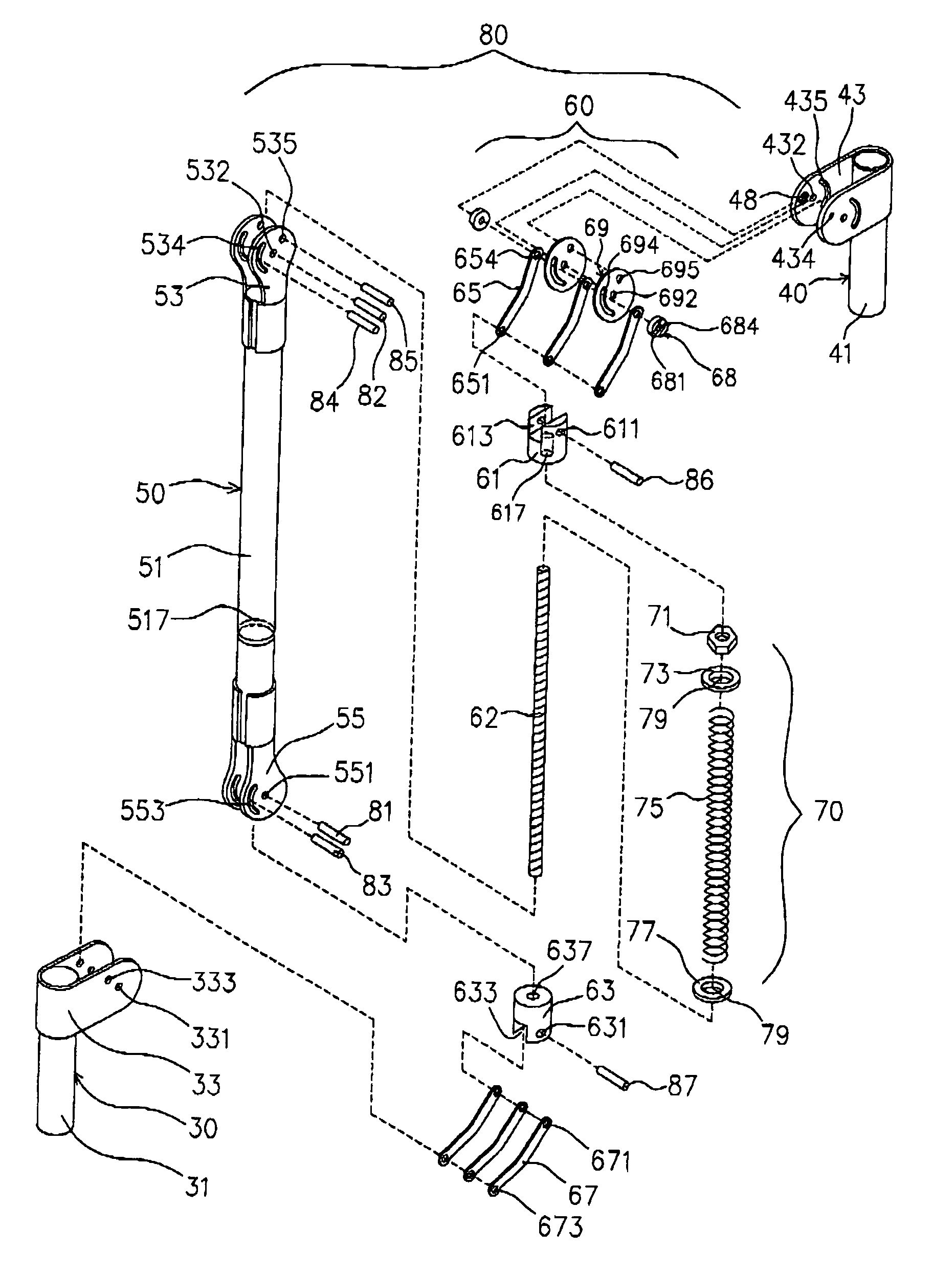
[0033]Please refer to FIGS. 4A and 4B. FIG. 4A is a perspective exploded diagram of a preferred embodiment of the present invention. FIG. 4B is a side cross-sectional view of a preferred embodiment of the present invention.

[0034]As shown in the figures, the present invention provides a support arm comprise a support chassis 30, a support cylinder 31, a connecting seat 40, a hang arm 50, a spring device 70 and a linked device 60.

[0035]The support chassis 30 includes a connecting cylinder 31, wherein at least one support wing 33 is provided at one end of the connecting cylinder 31, and a first support axle hole 331 and a second support axle hole 333 are provided on the proper positions of the support wing 33.

[0036]The connecting seat 40 includes a connecting cylinder 41, wherein the connecting cylinder 41 is provided with at least one connecting wing 43 at one end of the connecting cylinder 41. On the proper positions of the connecting wing 43, a ramp block 48 and a second connecting ...


PUM


Abstract

A self-locking support arm is provided, comprising a hang arm and a linked device between a support seat and a connecting seat, which forms a set of four parallel connected rods. Therefore, when the support arm moving up and down, the connecting seat will maintain a fixed angle. A spring device is disposed between the hang arm and the linked device to provide tension of auto homing to the support arm. And, in a rotating joint formed by the linked device and the support seat, a ramp block and a ramp slider block is engaged, to provide an effect of self-locking, and better loading capacity.

Description

BACKGROUND OF THE INVENTION[0001]1. Field of the Invention[0002]The present invention relates to a support arm. Especially, the present invention relates to a support arm, which is capable of automatically self-locking. The support arm not only has a function of being locked for positioning, but also has a benefit of supporting a heavier load.[0003]2. Description of the Related Art[0004]As the era and age of information technology comes, more and more processes or works must be done through the use of computer equipment, either in work or in live. However, computer equipments such as a mouse, a printer, a scanner, a display monitor, or a keyboard, takes a lot of space on the desk or table. Especially, when the desk is small, it is inconvenient to use or operate for a user. Notwithstanding the foregoing, when the computer equipments are installed, their height and angle are not suit for users of different sizes. As a result, injuries suffered on the job are open caused by using compu...

Claims


Application Information

Patent Timeline
Patent Type & Authority Patents(United States)
IPC IPC(8): E04G3/00A41D27/22F16M11/04F16M11/10
CPCF16M11/04F16M11/10F16M11/2064F16M13/02Y10S248/917F16M2200/044Y10S248/919Y10S248/922F16M2200/024
Inventor WANG, CHIA-MING
Owner SALLAS INDAL
Why Eureka
Try Eureka