
Locking nut and bolt system with enhanced locking

a technology of locking nut and bolt system, which is applied in the direction of threaded fasteners, screws, fastening means, etc., can solve the problems of loosening and unattaching of components forming the assembly, and achieve enhanced locking features, enhanced locking characteristics, and better fixed

Active Publication Date: 2007-03-13
PERMANENT TECH
View PDF66 Cites 20 Cited by
  • Summary
  • Abstract
  • Description
  • Claims
  • Application Information

AI Technical Summary

Benefits of technology

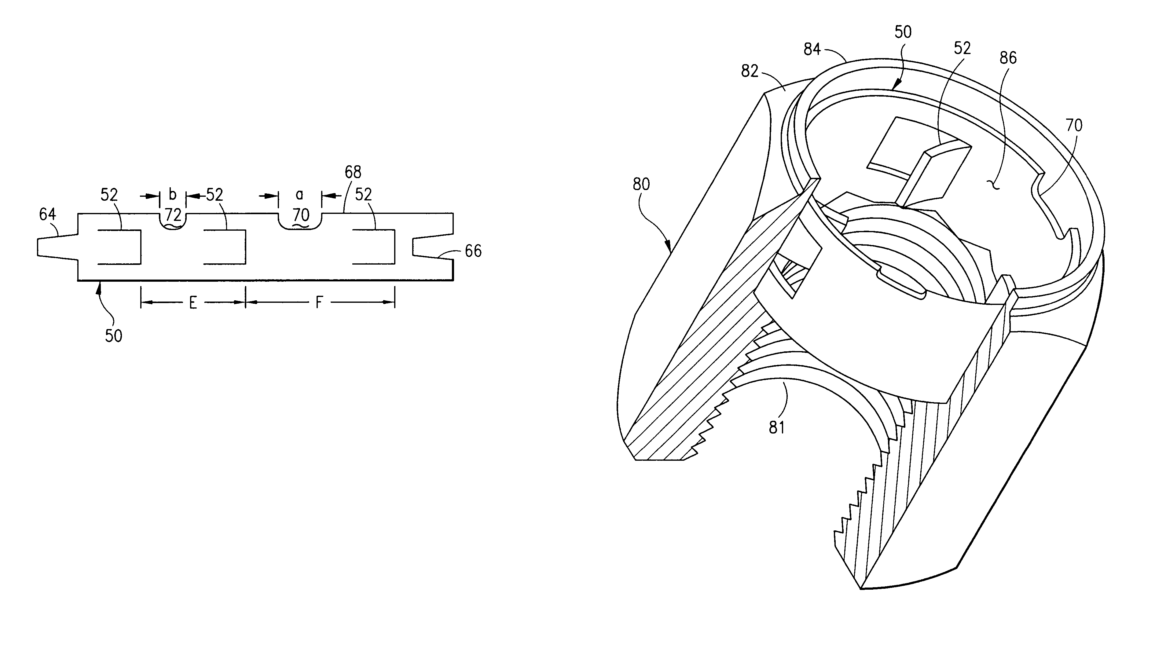
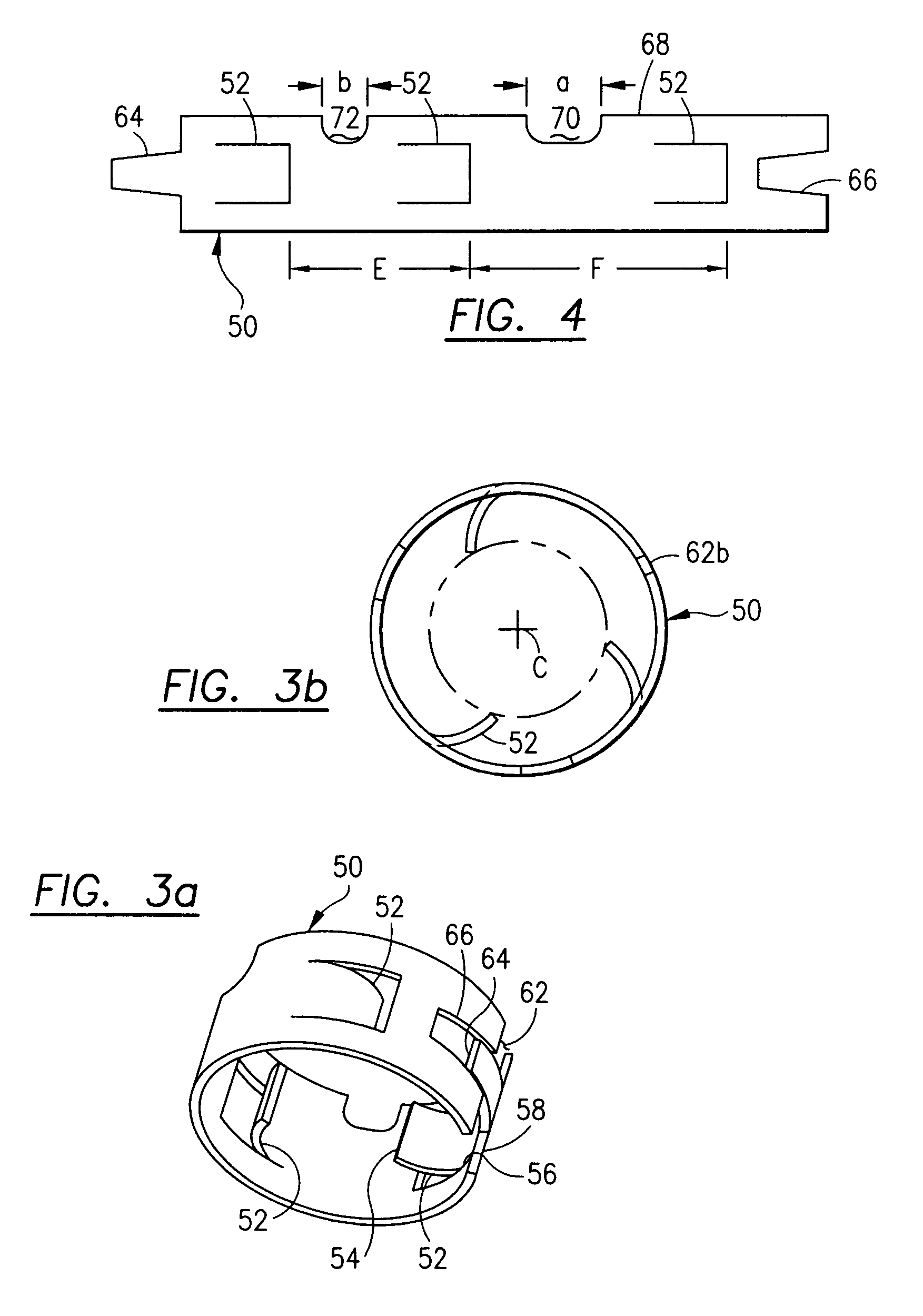
"The present invention provides a locking nut and bolt system with enhanced locking features. The locking nut insert carries a plurality of locking tines that are not radially symmetrical to each other, which enhances the locking characteristic of the system. The insert is better fixed within the nut due to half-moon cut-out edge segments. The locking action of a respective tine in a corresponding bolt groove is asynchronous with respect to other tines and other grooves on the locking unit insert and the bolt. The locking unit insert is longitudinally split to enhance handling and manufacturing characteristics of the locking unit insert. The elongated locking unit includes a plurality of at least three tines (in one embodiment) which protrude tangentially and generally radially inward towards the axial centerline of the bolt. The tines, in one embodiment, are radially asymmetrically disposed about the axial centerline such that when a respective tine latches into a corresponding groove, asynchronous locking operation is achieved with respect to the remaining tines and grooves. The elongated locking unit has half-moon cut-out edge segments that are swaged to the nut thereby prohibiting the locking unit insert from rotating within the nut recess. The elongated locking unit also includes a longitudinal split which enhances handling and manufacture of the locking unit insert."

Problems solved by technology

Sometimes, the mounted assembly is subjected to vibrations which cause counter-rotative torque on the nut and bolt such that the nut loosens on the bolt and the components forming the assembly become loose and unattached.

Method used


Image

  • Locking nut and bolt system with enhanced locking
  • Locking nut and bolt system with enhanced locking
  • Locking nut and bolt system with enhanced locking

Examples


Embodiment Construction

[0020]The present invention relates to a locking nut and bolt system (including a locking nut insert) with enhanced locking capabilities. A manufacturing process is also described for the locking unit insert.

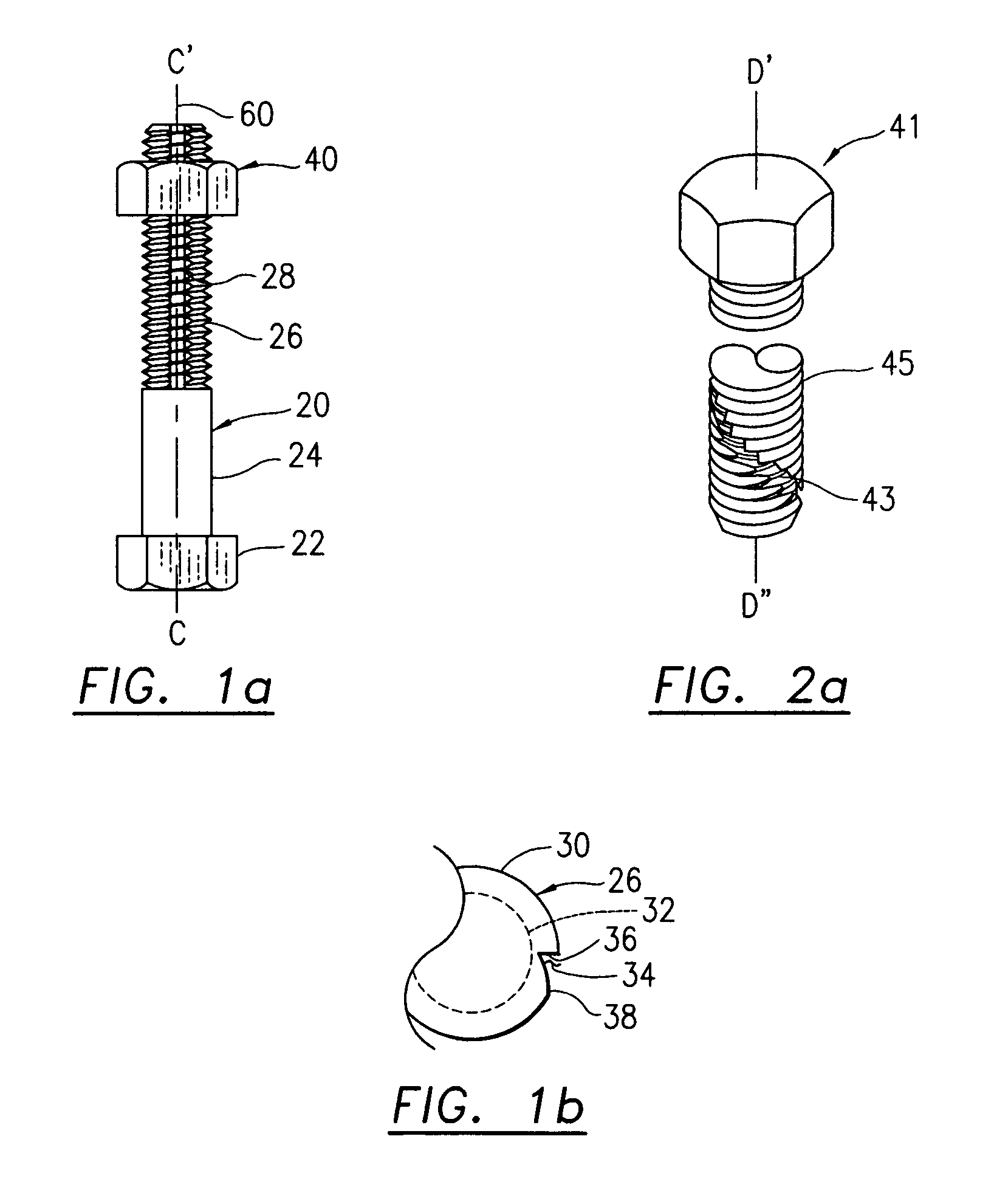
[0021]FIG. 1a diagrammatically illustrates a bolt 20 having a bolt head 22 and a bolt stem 24. Bolt 20 includes threads which include thread crests 26 and thread troughs 28. Nut 40 includes a plurality of threads which are complementary to the thread system 26, 28 on bolt stem 24. Axial centerline 60 is related to the axial centerline of the bolt 20 as well as nut 40. Axial thread end 31 is also shown in FIG. 1a. Reference to an outboard position of the locking nut insert (not shown in FIG. 1a) refers to items closer to axial thread end 31. The term “inboard” refers to items closer to bolt head 22.

[0022]FIG. 1b diagrammatically shows a cross-sectional view of grooved bolt 20. Particularly, thread crest 26 includes a generally longitudinal groove 34 thereat. Groove 34 includes a ...


PUM


Abstract

The locking nut and bolt system includes an elongated locking unit, mounted in a nut and operative with a specially configured groove bolt. The locking unit includes a plurality of at least three tines, asymmetrically located, which protrude tangentially and generally radially inward. The tines are radially asymmetrically disposed such that when a respective tine latches into a corresponding groove, asynchronous locking operation is achieved. When the tine is engaged in the groove, counter-rotational movement (loosening) is prohibited. In another embodiment, the locking unit has different sized edge cut-outs prohibiting the locking insert from rotating within the nut. The locking unit may also include a longitudinal split and a key and a keyway. A manufacturing process is also disclosed.

Description

[0001]The present invention relates to a locking nut and bolt system and a locking nut insert utilized in connection with a specially configured bolt to provide enhanced locking or resistance to counter-rotative motion. A manufacturing process for the locking unit insert is also disclosed.BACKGROUND OF THE INVENTION[0002]Nut and bolt systems typically compress elements therebetween and mount one component to another component. Sometimes, the mounted assembly is subjected to vibrations which cause counter-rotative torque on the nut and bolt such that the nut loosens on the bolt and the components forming the assembly become loose and unattached. It is helpful to have a locking nut and bolt system and a locking nut insert (operable in conjunction with a specially configured bolt) which prohibits counter-rotative movement and therefore maintains the components in a mounted or fixed assembly.[0003]Various locking nut and bolt systems are disclosed in U.S. Pat. No. 6,010,289 to DiStasio;...

Claims


Application Information

Patent Timeline
Patent Type & Authority Patents(United States)
IPC IPC(8): F16B39/32
CPCF16B39/32
Inventor BALL, LOREN
Owner PERMANENT TECH
Learn More