Wide-band fractal antenna

a fractal antenna and wideband technology, applied in the direction of antennas, elongated active element feeds, antenna feed intermediates, etc., can solve problems such as bandwidth reduction

Active Publication Date: 2007-03-13
FRACTAL ANTENNA SYST
View PDF8 Cites 35 Cited by
  • Summary
  • Abstract
  • Description
  • Claims
  • Application Information

AI Technical Summary

Problems solved by technology

Being held to particular size constraints, the bandwidth performance for antenna designs such as discone and bicone antennas is sacrificed resulted in reduced bandwidth.

Method used


Image

  • Wide-band fractal antenna
  • Wide-band fractal antenna
  • Wide-band fractal antenna

Examples


Embodiment Construction

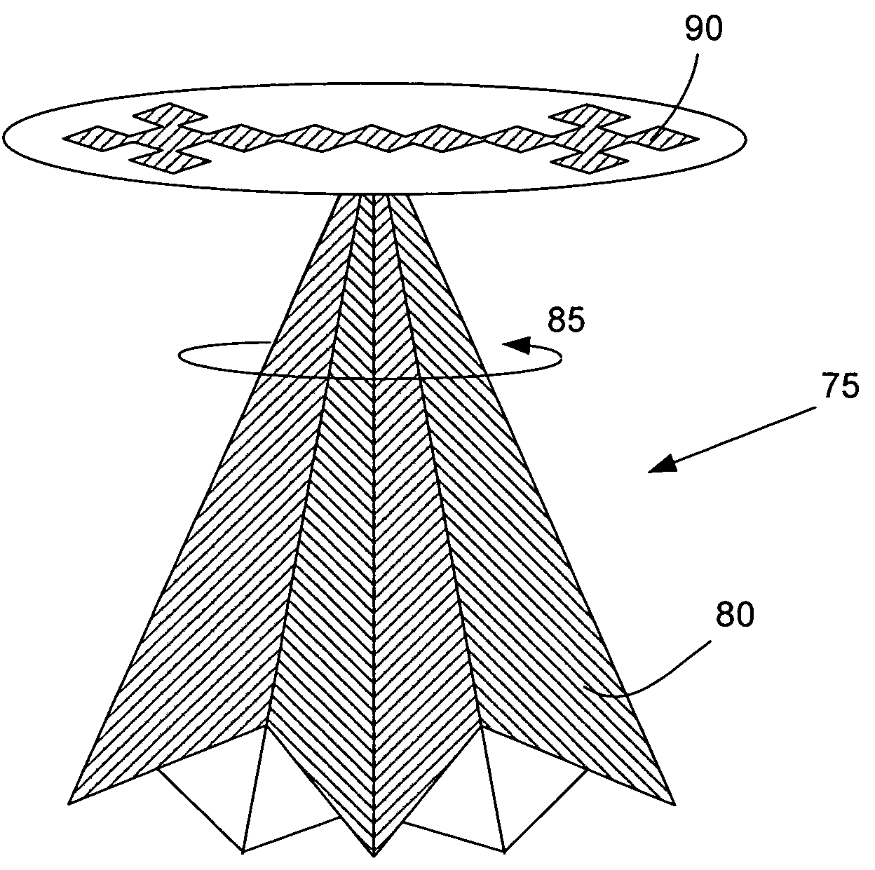
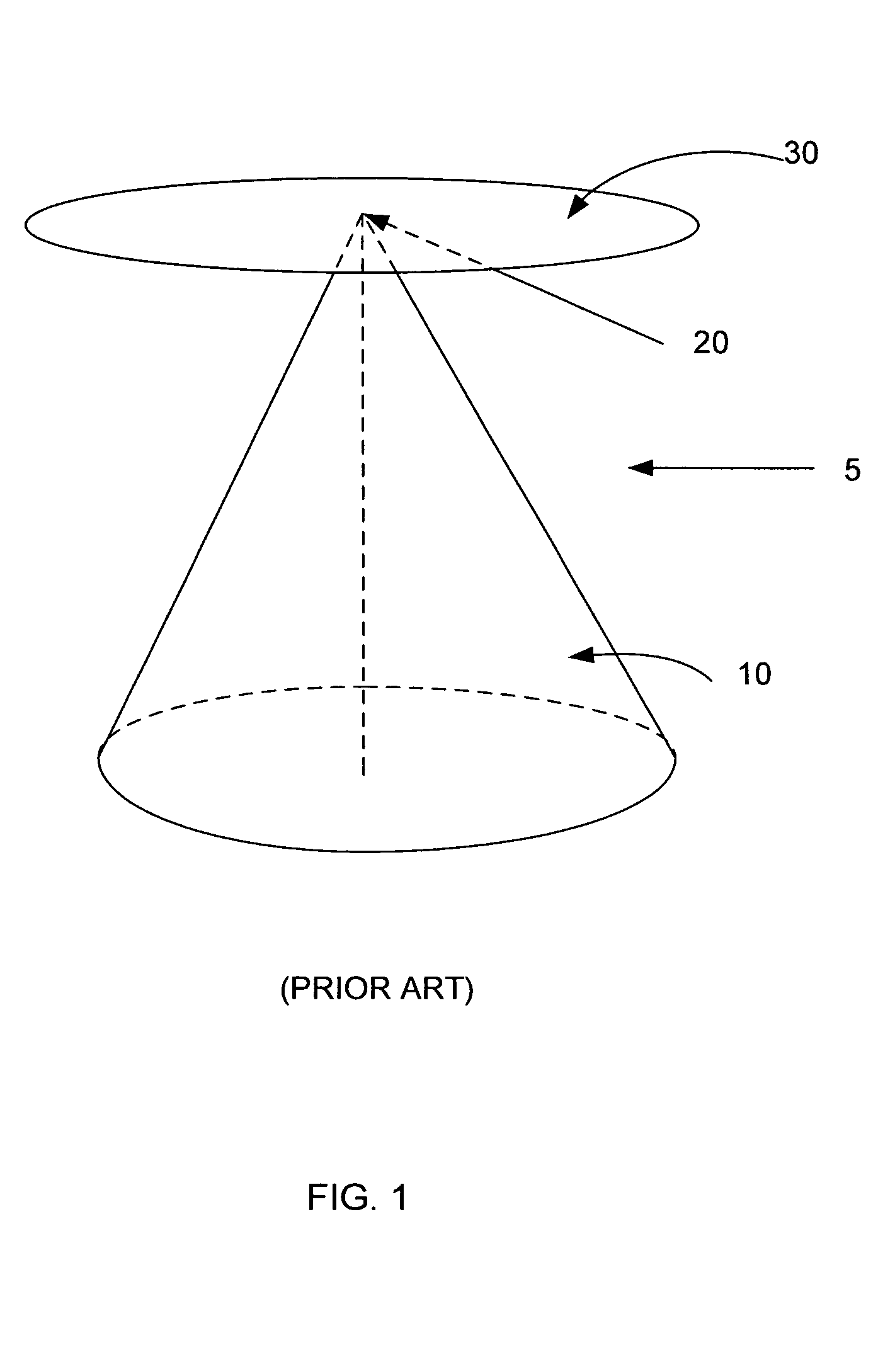
[0017]In general, a wideband requirement for an antenna, especially a dipole-like antenna, has required a bicone or discone shape to afford the performance desired over a large pass band. For example, some pass bands exceed 3:1 as a ratio of the highest to lowest frequencies of operation, and typically ratios of 20:1 to 100:1 are desired. Referring to FIG. 1, prior art discone antenna 5 includes a sub-element 10 shaped as a cone the apex of which is attached to one side of a feed system at location 20. A second sub-element 30 is attached to the other side of the feed system, such as the braid of a coaxial feed system. This sub-element is a flat disk mean to act as a counterpoise.

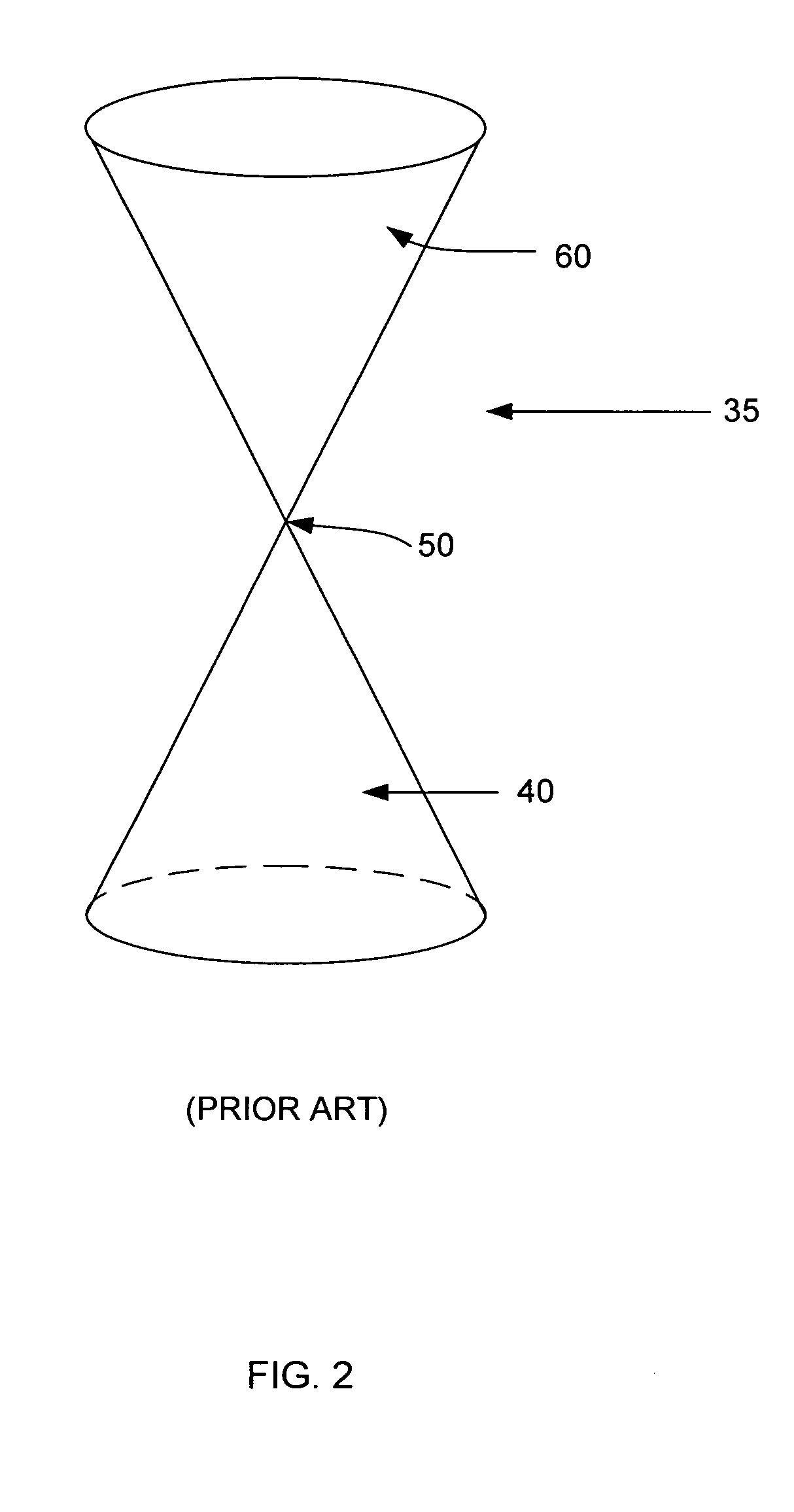
[0018]Referring to FIG. 2, another current antenna design is depicted that includes a bicone antenna 35, in which a sub-element 40 is arranged similar to sub-element 10 shown the discone antenna 5 of FIG. 1 with a similar feed arrangement at location 50. However, for bicone antenna 35 rather than a second su...


PUM


Abstract

An apparatus includes a discone antenna including a cone-shaped element whose physical shape is at least partially defined by at least one pleat.

Description

CROSS-REFERENCE TO RELATED APPLICATIONS[0001]This application is related to the following U.S. applications, of common assignee, from which priority is claimed, and the contents of which are incorporated herein in their entirety by reference: U.S. Application No. 60 / 458,333 (Filed Mar. 29, 2003)BACKGROUND OF THE INVENTION[0002]The present invention relates to wideband performance antenna, and more particularly, to discone or bicone antenna.[0003]Antenna are used to radiate and / or receive typically electromagnetic signals, preferably with antenna gain, directivity, and efficiency. Practical antenna design traditionally involves trade-offs between various parameters, including antenna gain, size, efficiency, and bandwidth. Antenna size is also traded off during antenna design that typically reduces frequency bandwidth. Being held to particular size constraints, the bandwidth performance for antenna designs such as discone and bicone antennas is sacrificed resulted in reduced bandwidth...

Claims


Application Information

Patent Timeline
Patent Type & Authority Patents(United States)
IPC IPC(8): H01Q13/00H01Q5/00H01Q9/28H01Q9/40
CPCH01Q9/40H01Q9/28
Inventor COHEN, NATHAN
Owner FRACTAL ANTENNA SYST
Why Eureka
Try Eureka