
Method and apparatus for performing fast handover through fast ranging in a broadband wireless communication system

a wireless communication system and fast ranging technology, applied in wireless communication, wireless communication, network topologies, etc., can solve the problems of unexpected considerable delay, waste of network resources, quality degradation, etc., and achieve the effect of effective operation of a ranging process, more rapidly performing handover, and fast handover

Inactive Publication Date: 2005-09-01
SAMSUNG ELECTRONICS CO LTD
View PDF7 Cites 290 Cited by
  • Summary
  • Abstract
  • Description
  • Claims
  • Application Information

AI Technical Summary

Benefits of technology

[0034] It is, therefore, an object of the present invention to provide a method and apparatus for more effectively operating a ranging process in a broadband wireless access communication system using a cellular scheme.
[0035] It is another object of the present invention to provide a method and apparatus for more rapidly performing a handover by receiving an allocated temporary connection identifier (CID) from a target base station during the scanning for a handover in a broadband wireless access communication system.
[0036] It is further another object of the present invention to provide a method and apparatus for more rapidly performing handover by effectively estimating a round trip delay (RTD) for a target base station, required for a handover, by a subscriber station in a broadband wireless access communication system.
[0037] It is yet another object of the present invention to provide a method and apparatus for more rapidly performing a handover by performing fast ranging with a target base station based on a short-length CID during handover in a broadband wireless access communication system.

Problems solved by technology

The conventional technology is disadvantageous in that an SS undergoing handover performs the competition-based ranging transmission in a network topology acquisition process or a network re-entry process.
This may cause not only a waste of network resources but also an unexpected considerable delay, and becomes a direct cause of quality deterioration of service traffic for an SS attempting a handover.
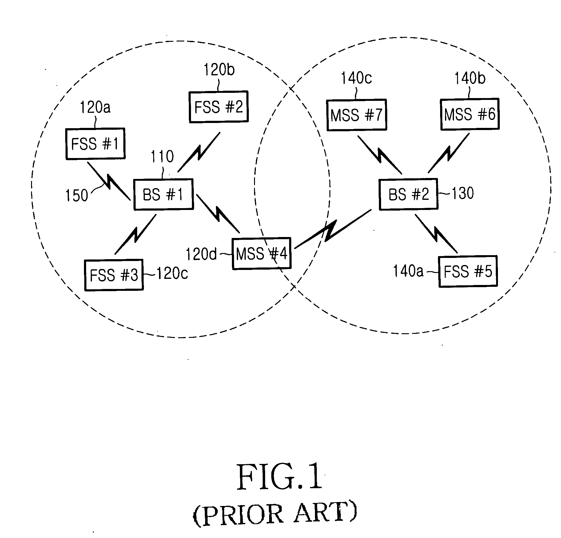
Further, in the conventional method, when a target BS allocates an information element for fast ranging, the target BS is required to allocate resources capable of accepting a maximum RTD as described above, causing an inefficient use of the resources, and an unexpected considerable delay is caused by a competition-based ranging request occurring in the scanning process.

Method used


Image

  • Method and apparatus for performing fast handover through fast ranging in a broadband wireless communication system
  • Method and apparatus for performing fast handover through fast ranging in a broadband wireless communication system
  • Method and apparatus for performing fast handover through fast ranging in a broadband wireless communication system

Examples


first embodiment (

Active Scanning-Based Handover Procedure)

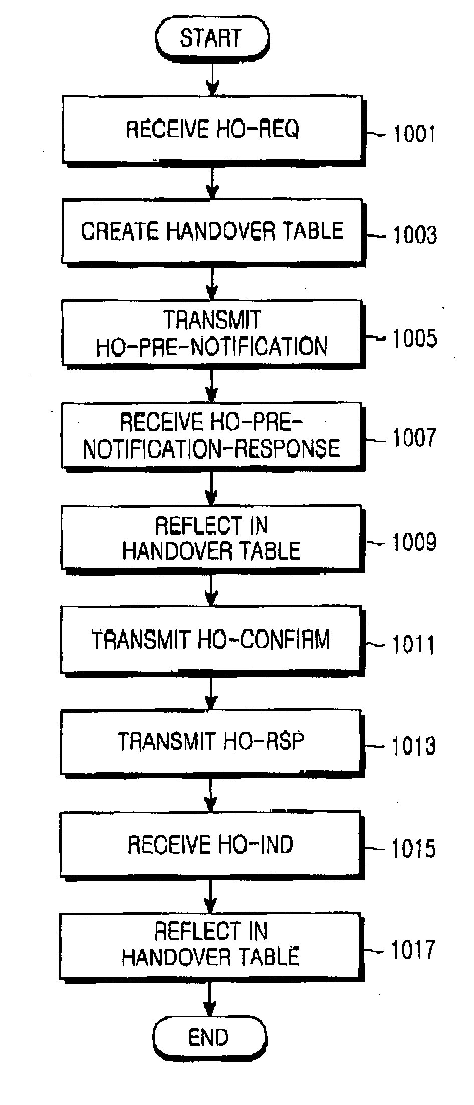
[0070]FIG. 6 is a signaling diagram illustrating an active scanning-based handover procedure through fast ranging according to a first embodiment of the present invention. Referring to FIG. 6, a handover method according to the first embodiment of the present invention allocates uplink resources through a 16-bit CID instead of a 48-bit MAC address of an SS used in the conventional fast ranging method.

[0071] Referring to FIG. 6, an SS#1610 requiring a handover transmits a Scanning Request (SCN-REQ) message to a BS#1620 (Step 641), and receives a Scanning Response (SCN-RSP) message from the BS#1620 in response to the SCN-REQ message (Step 643). Thereafter, the SS#1610 transmits an initial Ranging Request (RNG-REQ) message to a BS#2630 according to an active scanning process (Step 645). The BS#2630 transmits a Ranging Response (RNG-RSP) message to the SS#1610 in response to the RNG-REQ message (Step 647). At this point, the BS#2630 can allocate...

second embodiment (

IIR-Based Handover Procedure)

[0078]FIG. 7 is a signaling diagram illustrating a passive scanning-based handover procedure through fast ranging according to the second embodiment of the present invention. FIG. 7 illustrates an IIR procedure for fast handover proposed in the present invention, wherein during a network topology acquisition process performed during handover, an SS estimates an RTD value of a target BS simply by using an arrival time difference between reference signals transmitted from a serving BS and the target BS, without transmitting / receiving ranging messages to / from the target BS.

[0079] Referring to FIG. 7, an SS#1710 desiring to perform handover receives periodic downlink frame preambles (DFP) 741a, 741b, 741c, 745 and 749 each having a TDD / FDD frame duration period, from a BS#1720. The SS#1710 can generate and correct its own clock based on the DFP signals 741a, 741b, 741c, 745 and 749 periodically transmitted from the BS#1720. If a carrier-to-interference and ...


PUM


Abstract

A method for performing a handover by a subscriber station (SS) in a broadband wireless communication system including a serving base station (BS) communicating with the SS, and at least one neighbor BS neighboring the serving BS. The SS receives downlink signals from the serving BS and the neighbor BS; measures an arrival time difference between the downlink signal received from the serving BS and the downlink signal received from the neighbor BS; and transmits the measured arrival time difference to the serving BS.

Description

PRIORITY [0001] This application claims priority under 35 U.S.C. § 119 to an application entitled “Method and Apparatus for Performing Fast Handover through Fast Ranging in a Broadband Wireless Communication System” filed in the Korean Intellectual Property Office on Feb. 13, 2004 and assigned Serial No. 2004-9517, the contents of which are incorporated herein by reference. BACKGROUND OF THE INVENTION [0002] 1. Field of the Invention [0003] The present invention relates generally to a broadband wireless communication system, and in particular, to a method and apparatus for performing fast handover using fast ranging. [0004] 2. Description of the Related Art [0005] A broadband wireless access communication system which is now under discussion in an Institute of Electrical and Electronics Engineers (IEEE) 802.16 standardization group performs point-to-multipoint communication between a base station (BS) and a subscriber station (SS). A physical (PHY) layer standard defines Time Divisi...

Claims


Application Information

Patent Timeline
IPC IPC(8): H04L12/28H04B7/26H04W36/12
CPCH04W36/12H04W36/0077H04W84/12H04W36/0061E04H15/34E04H15/60
Inventor HONG, SEUNG-EUNSONG, BONG-GEEEOM, KWANG-SEOPCHO, MIN-HEEJU, HYEONG-JONG
Owner SAMSUNG ELECTRONICS CO LTD
Learn More