Apparatus and method for continuous noninvasive measurement of respiratory function and events

Active Publication Date: 2011-03-10
LIFEWAVE BIOMEDICAL
View PDF105 Cites 291 Cited by
  • Summary
  • Abstract
  • Description
  • Claims
  • Application Information

AI Technical Summary

Benefits of technology

[0059]The method may also include the steps of: wherein said at least one additional metric is identification and verification of completeness of a target respiratory structure as the respiratory structure changes over time, by evaluating the sustained and rhythmic behavior of the respiration-influenced anatomical elements, wherein the IRV

Problems solved by technology

Currently, there are various methods used to assess the function of each breathing mechanism component, however no single device is known that can easily, conveniently and accurately evaluate the overall performance of breathing.
It is important to note that all of the above approaches fail to obtain direct information concerning the both the mechanical aspects of the respiratory process and the physiological changes within the lungs themselves during the respiratory process.
Breathing masks, however, are generally not well tolerated by patients for extended periods of time.
Additionally, such masks are not convenient for ambulatory patients.
Each of the above existing methods is relatively complex, expensive and somewhat invasive.
They do not lend themselves to use outside a hospital or doctor's office.
Lung capacity can also be affected by altitude.
Hence, the smoker engaged in exercise will most likely experience an oxygen deficit due to existing damage to the lungs which prevents perfusion of a greater volume of the lung area.
Lower respiratory tract infections place a considerable strain on the health budget and are generally more serious than upper respiratory infections.
Each of these typically present with symptoms of shortness of breath.
Congestive heart failure is often undiagnosed due to a lack of a universally agreed definition and difficulties in diagnosis, particularly when the condition is considered “mild”.
Given that the left side of the heart pumps blood from the lungs to the organs, failure to do so leads to congestion of the lung veins and sympto

Method used


Image

  • Apparatus and method for continuous noninvasive measurement of respiratory function and events
  • Apparatus and method for continuous noninvasive measurement of respiratory function and events
  • Apparatus and method for continuous noninvasive measurement of respiratory function and events

Examples


first embodiment

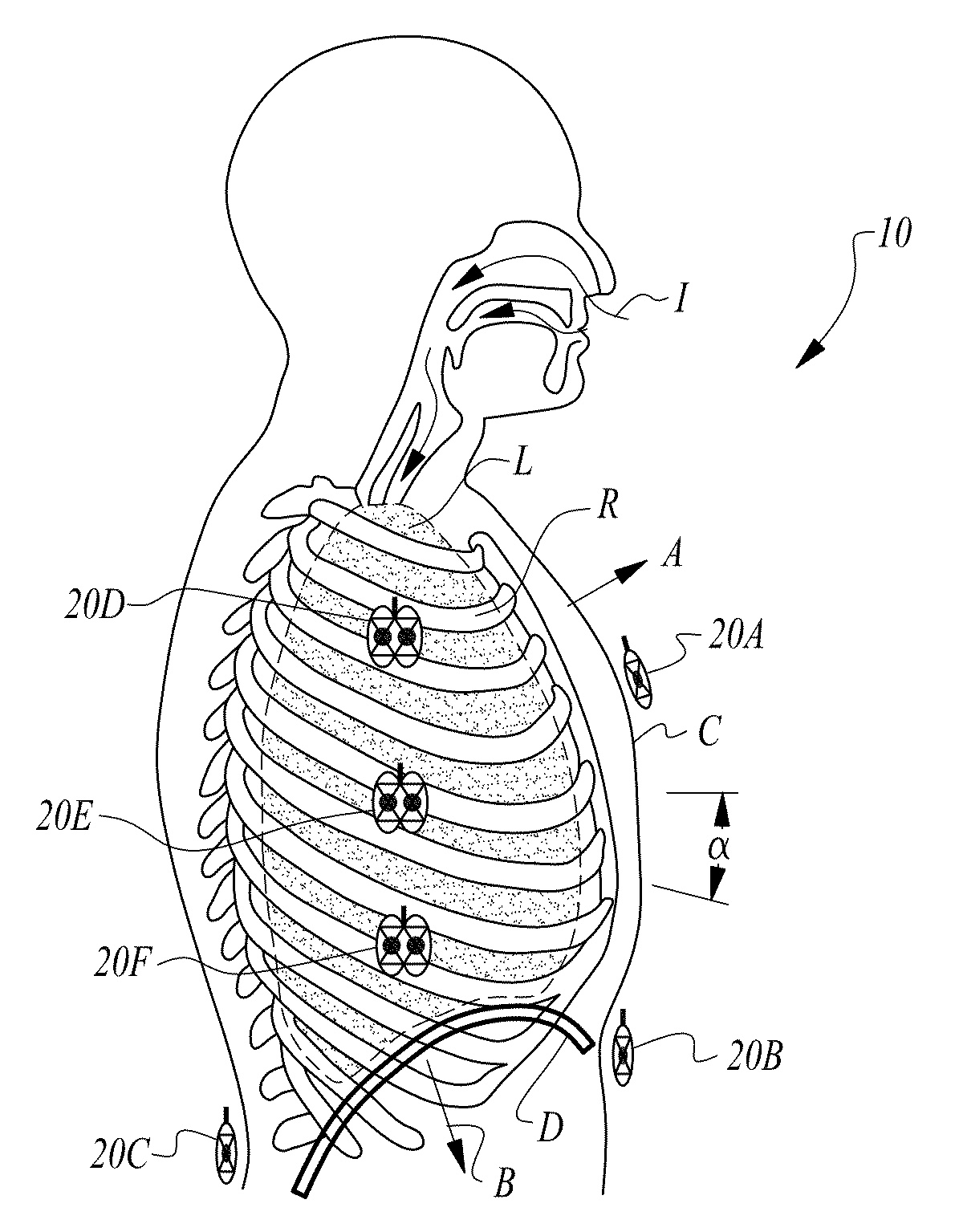
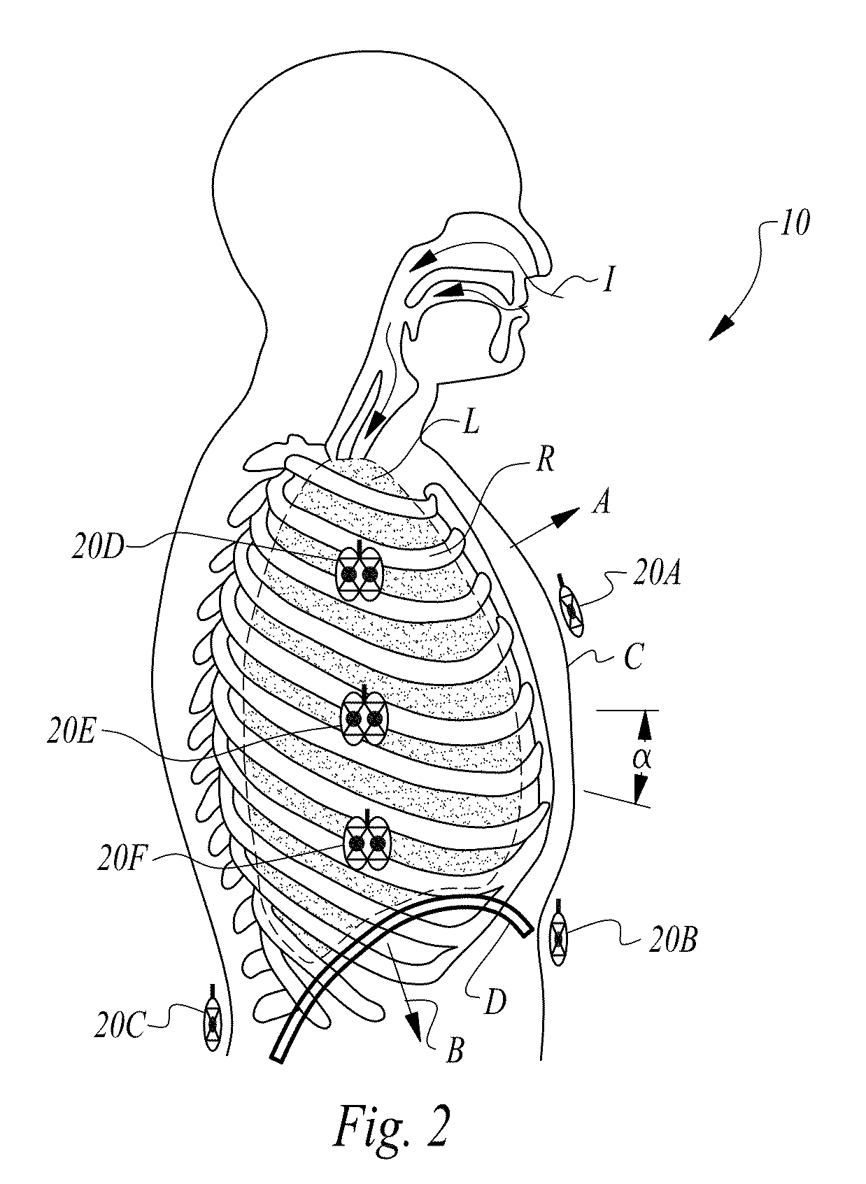
[0132]In a first embodiment, as illustrated in FIGS. 2 and 3, the apparatus 10 of the present invention captures and measures the motion of multiple anatomical elements during a respiratory cycle, where the motion is induced by various types of breathing. One or more sensors 20 transmit signals toward target areas and capture reflected signals which are then processed by the sensor to develop a qualitative and quantitative assessment of respiratory performance and health. To understand the operation of the apparatus 10 of the present invention, it is helpful for the reader to understand fundamental aspects of the physiological mechanics of breathing and how the apparatus 10 uniquely evaluates and tracks movement of the anatomical structure to generate various relevant respiratory parameters or metrics. The subsequent discussion of breathing mechanics, taken in conjunction with the respiratory disease information provided in the Background section of this document, will provide an un...

embodiment 100

[0161]The wireless sensors 120 are deployed to target or interrogate various portions or regions of the upper thorax associated with respiratory functionality. For example, wireless sensor 120C is located in the center of the chest adjacent a midpoint of the sternum to capture both cardiac and respiratory motion. Five additional sensors 120L are located adjacent specific portions of a subject's lungs L to monitor the performance and functionality of each lobe of each lung L independently of the other lobes. Additional wireless sensors 120S are deployed along the subject's side in proximity to each lobe of each lung to provide an alternative measure of motion and functionality for each lobe. In addition to the wireless sensors 120 deployed about the chest of the subject, the present multi-sensor embodiment 100 also includes a wireless sensor 120W preferably located at the middle of a subject's waist, held by a belt or waistband 112 to target movement of the diaphragm D. Sensor 120W m...

embodiment 200

[0165]Following are illustrative examples of specific anatomical motion to be monitored and tracked by the sensors 220. This motion is correlated and aggregated to develop the various measures and metrics of respiratory performance relative to various disease states. The data collected may be aggregated and disaggregated as necessary to support a plethora of different analyses relative to the condition being evaluated. For example, during deep breathing, one would expect the manubrium sterni to move 30 mm in an upward direction and 14 mm in a forward direction during inspiration. Additionally, the width of the subcostal angle, at a level of 30 mm below the articulation between the body of the sternum and the xiphoid process, is increased by 26 mm. Further, the umbilicus is retracted and drawn upward for a distance of 13 mm. By measuring these and other movements induced by respiration, the multiple wired sensor embodiment 200 of the present invention obtains mechanical motion data t...


PUM


Abstract

An apparatus and method for non-invasive and continuous measurement of respiratory chamber volume and associated parameters including respiratory rate, respiratory rhythm, tidal volume, dielectric variability and respiratory congestion. In particular, a non-invasive apparatus and method for determining dynamic and structural physiologic data from a living subject including a change in the spatial configuration of a respiratory chamber, a lung or a lobe of a lung to determine overall respiratory health comprising an ultra wide-band radar system having at least one transmitting and receiving antenna for applying ultra wide-band radio signals to a target area of the subject's anatomy wherein the receiving antenna collects and transmits signal returns from the target area.

Description

CROSS REFERENCE TO RELATED APPLICATION[0001]This application claims the benefit under 35 U.S.C. 119 of U.S. Provisional Patent Application No. 61 / 164,772, filed Mar. 30, 2009, titled “APPARATUS AND METHOD FOR CONTINUOUS NONINVASIVE MEASUREMENT OF RESPIRATORY FUNCTION AND EVENTS”.[0002]This application may be related to co-pending U.S. patent application Ser. No. 10 / 456,290 titled “SYSTEM AND METHOD FOR EXTRACTING PHYSIOLOGICAL DATA USING ULTRA-WIDEBAND RADAR AND IMPROVED SIGNAL PROCESSING TECHNIQUES”, filed on Jun. 2, 2003.INCORPORATION BY REFERENCE[0003]All publications and patent applications mentioned in this specification are herein incorporated by reference to the same extent as if each individual publication or patent application was specifically and individually indicated to be incorporated by reference.FIELD OF THE INVENTION[0004]The present invention relates in general to respiratory monitoring. More particularly, the present invention relates to an apparatus and method for...

Claims


Application Information

Patent Timeline
IPC IPC(8): A61B5/05
CPCA61B5/0507A61B5/0803A61B5/0816A61B5/087A61B5/091A61B5/0002A61B5/6804A61B5/6805A61B5/6831A61B5/6833A61B2560/0412A61B5/1135A61B5/1075
Inventor TUPIN, JR., JOE PAULTUPIN, JOE PAULMURRAY, JR., KENNETH ARLANTUPIN, JOHN DAVID
Owner LIFEWAVE BIOMEDICAL
Why Eureka
Try Eureka