Systems and methods for measuring picoampere current levels

a picoampere current and system technology, applied in the field of capacitance feedback integrators, can solve the problems of limited measurement of picoampere current levels with high bandwidth, basic limitation of resistive feedback op-amp circuits, and thermal noise associated with limiting noise, so as to reduce the capacitance of integrating capacitors, reduce the extraneous wiring capacitance, and the general node capacitance level of the integrated circuit version.

Inactive Publication Date: 2006-02-14
AGILENT TECH INC
View PDF13 Cites 21 Cited by
  • Summary
  • Abstract
  • Description
  • Claims
  • Application Information

AI Technical Summary

Benefits of technology

[0007]Representative embodiments enable picoampere current levels to be measured with bandwidths equal to or greater than 100 kHz. Representative embodiments enable such current measurements to occur by implementing the preamplifier of the integrator topology in integrated circuit form. By utilizing an integrated circuit form, the internal capacitance achieves significant advantages relative to a preamplifier constructed from discrete components mounted on a circuit board. For example, the general node capacitance level of the integrated circuit version is appreciably smaller. The load capacitances that the op-amps drive are also smaller, since the dimensions of the devices and the interconnect of the integrated circuit are smaller than the component counterparts for a structure realized on a circuit board. Moreover, the presence of the op-amps and interconnect components on an integrated circuit eliminates the necessity for electrostatic discharge (ESD) protection devices associated with each component of the preamplifier circuitry. By eliminating the ESD protection devices, the node capacitances may be maintained at a suitably low level. Also, the reduction in extraneous wiring capacitance enables further reduction of the capacitance of the integrating capacitors.
[0008]It shall be appreciated that the reduction of capacitance of the integrating capacitors affects the errors caused by the injection of charge due to the resets of the integrator capacitors. Specifically, when the internal capacitance is reduced, a smaller amount of injected charge will cause a greater deviation between the input current and the measured current. Representative embodiments adapt to the increased sensitivity to charge injection utilizing a plural number of mechanisms. Specifically, representative embodiments provide charge injection compensation structure to phase reversal switches to address unbalanced impedances on the input side of the phase reversal switches. Secondly, representative embodiments utilize slightly different operating points for inputs to the integrator op-amp. By utilizing a variety of charge injection compensation mechanisms, representative embodiments reduce the net charge injection to sufficiently low levels to maintain the switching transients to prevent appreciable corruption of the current measurement.

Problems solved by technology

Resistive feedback op-amp circuits suffer from a basic limitation.
Specifically, the measurement of picoampere current levels with high bandwidth is limited by the noise of the preamplifier system converting the small input current into a larger signal for subsequent signal processing.
In applications using resistive feedback, the limiting noise is the thermal noise associated with the feedback resistor.
Accordingly, the transresistance through the preamplifier circuitry may not be sufficiently large to dominate the noise of the subsequent signal processing stages.
The dominant noise limitation for circuits implemented according to the '790 topology is:

Method used


Image

  • Systems and methods for measuring picoampere current levels
  • Systems and methods for measuring picoampere current levels
  • Systems and methods for measuring picoampere current levels

Examples


Embodiment Construction

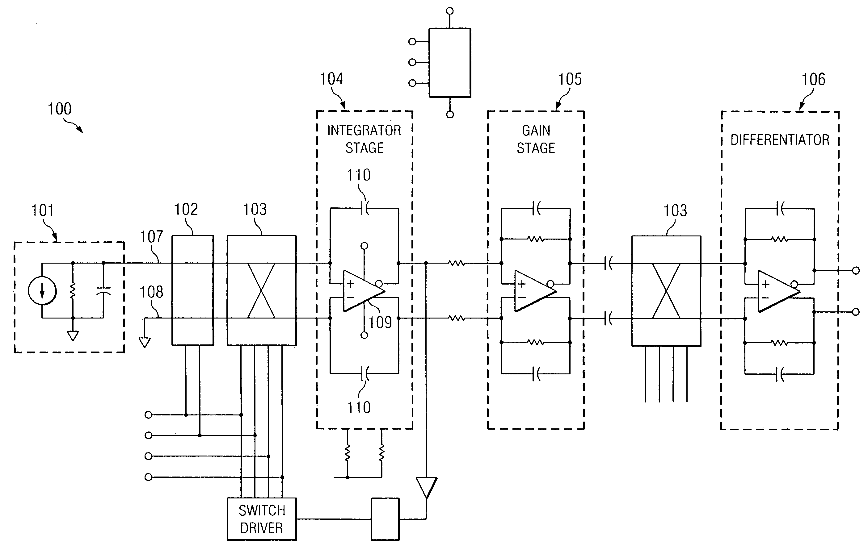
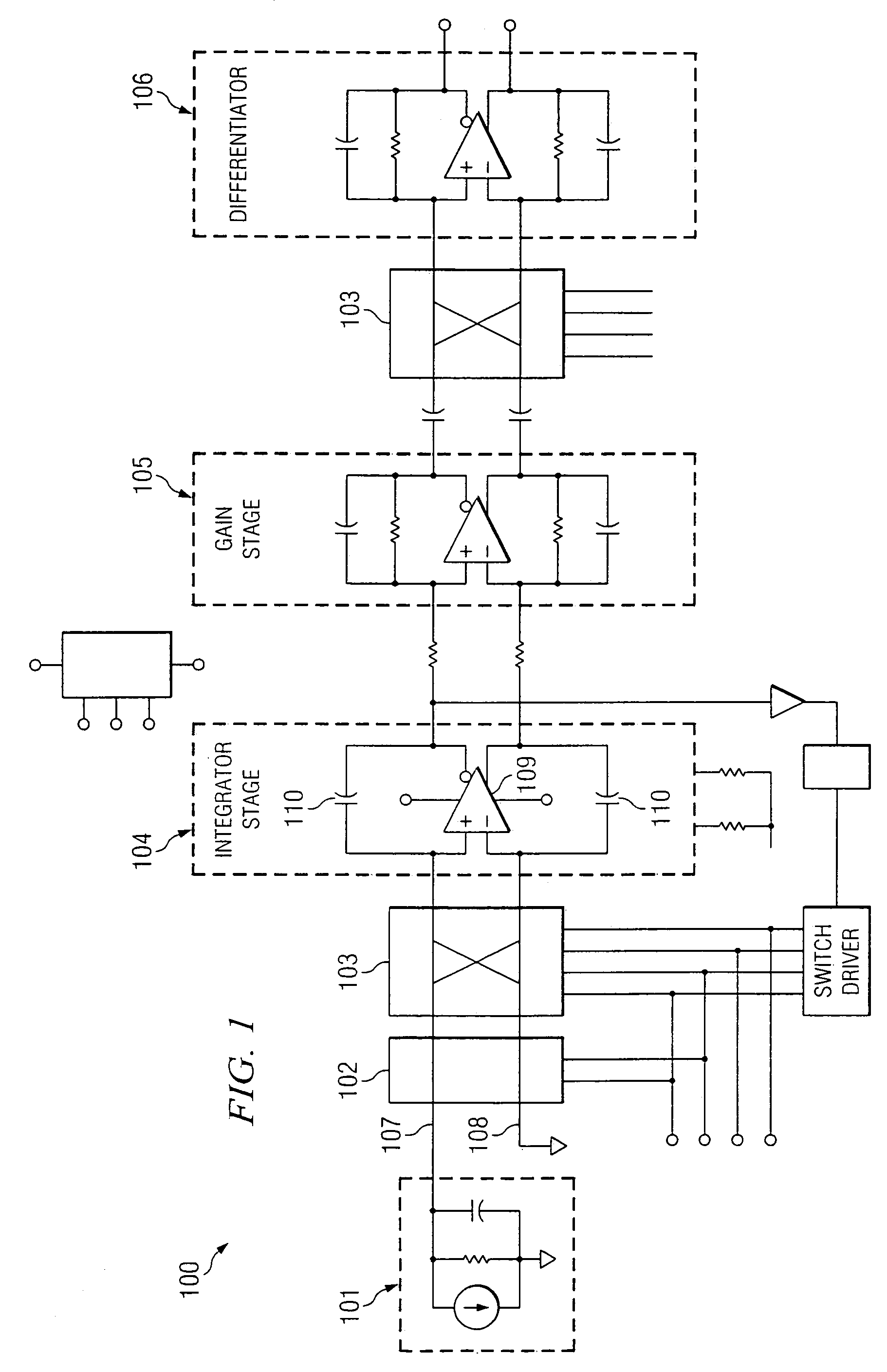
[0015]Referring now to the drawings, FIG. 1 depicts a schematic of picoammeter 100 according to representative embodiments. Picoammeter 100 may be advantageously implemented as an integrated circuit to reduce the internal capacitance and to increase the current measurement bandwidth to 100 kHz or greater as previously discussed.

[0016]Picoammeter 100 includes a plurality of stages. First stage model 101 represents a source of low level current to be measured by picoammeter 100. Picoammeter 100 includes integrator 104 with capacitive feedback elements 110. One of the capacitive feedback elements 110 couples the positive input of op-amp 109 to the negative output of op-amp 109. Likewise, the other one of capacitive feedback elements 110 couples the negative input of op-amp 109 to the positive output of op-amp 109. Capacitive feedback elements 110 may possess relatively low capacitance (e.g., 0.2 pF) to enable the bandwidth of integrator 104 to be increased.

[0017]Picoammeter 100 further...


PUM


Abstract

In one embodiment, a circuit measures picoampere current levels. The circuit comprises: an operational-amplifier that has differential inputs and differential outputs; a switching structure that switchably couples an input line to one of the differential inputs in response signals from a timing circuit; a first integrating capacitor coupled to one of the differential inputs and to one of the differential outputs; a second integrating capacitor coupled to the other of the differential inputs; and a charge injection compensation structure that selectively injects charge into the input line and removes charge from the input line in response to signals from the timing circuit.

Description

TECHNICAL FIELD[0001]Representative embodiments are directed to a capacitive feedback integrator that includes charge injection compensation functionality that is suitable for measuring picoampere current levels.BACKGROUND OF THE INVENTION[0002]A common method of converting a small current signal into output voltage signal utilizes an operational amplifier (op-amp) and a resistive feedback element to convert from input current to output voltage. An implementation of this method is described in chapter four, pages 175–261, of The Art of Electronics 2nd edition, Horowitz, P. and Hill, W., Cambridge University Press (1989). Resistive feedback op-amp circuits suffer from a basic limitation. Specifically, the measurement of picoampere current levels with high bandwidth is limited by the noise of the preamplifier system converting the small input current into a larger signal for subsequent signal processing. In applications using resistive feedback, the limiting noise is the thermal noise...

Claims


Application Information

Patent Timeline
Patent Type & Authority Patents(United States)
IPC IPC(8): G01R31/08G01R19/00G01R22/00G01R31/28
CPCG01R31/2884G01R19/0092
Inventor BAUMGARTNER, RICHARD A.
Owner AGILENT TECH INC
Why Eureka
Try Eureka