Method for determining a die profile for forming a metal part having a desired shape and associated methods

a metal part and die-cutting technology, applied in the direction of shaping tools, instruments, electric programme control, etc., can solve the problems of time-consuming and cost prohibitive to use this trial-and-error procedure for die development, ineffective old “rules of thumb” and the accumulated wisdom and experience of the designer, and the cost of “tool recutting” can exceed a half-million dollars

Inactive Publication Date: 2007-03-20
ARCONIC INC
View PDF7 Cites 18 Cited by
  • Summary
  • Abstract
  • Description
  • Claims
  • Application Information

AI Technical Summary

Problems solved by technology

However, problems arise when new materials, such as high strength steel or aluminum are desired to be formed.
When using these new materials, the old “rules of thumb” and the accumulated wisdom and experience of the designer sometimes prov...

Method used


Image

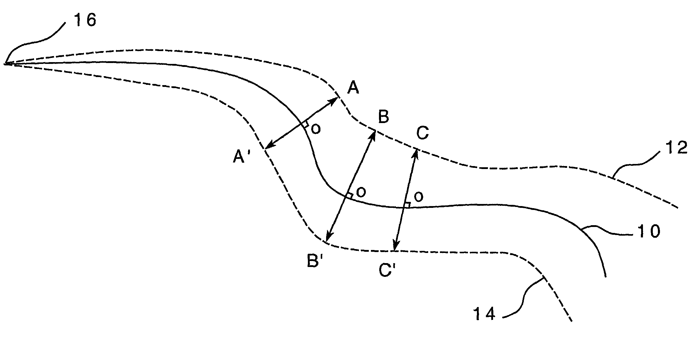
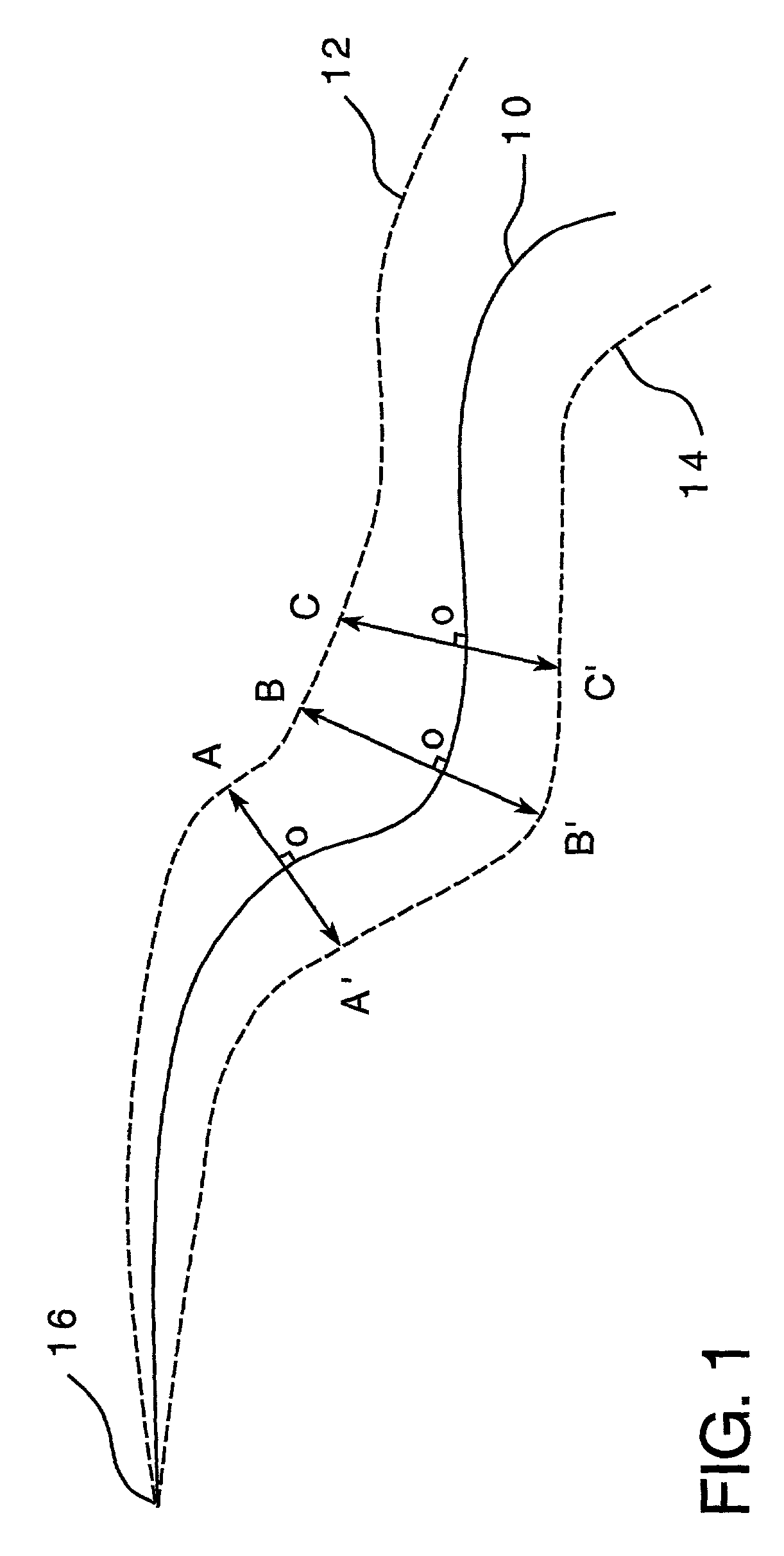
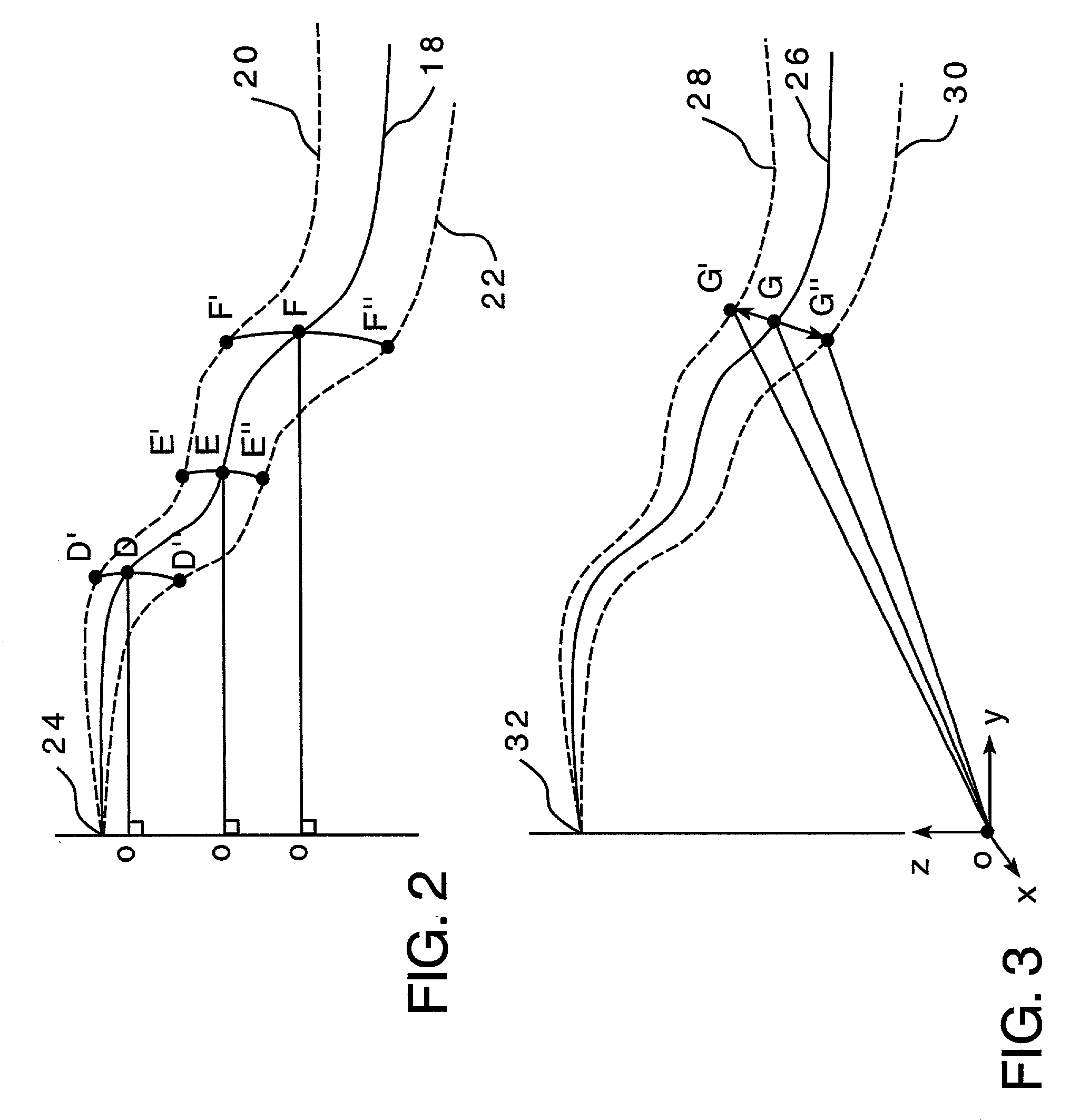
  • Method for determining a die profile for forming a metal part having a desired shape and associated methods
  • Method for determining a die profile for forming a metal part having a desired shape and associated methods
  • Method for determining a die profile for forming a metal part having a desired shape and associated methods

Examples


example

[0038]It was desired to obtain a metal product shape by defining the required die shape and forming process which delivers part tolerance of ±2 mm relative to the nominal design on a single 2D curvature part design. The purpose of this study was to evaluate a method of compensating for springback and to fiber validate the accuracy of the finite element analysis (FEA) used to model the forming process. For the first portion of the study, the die profiles were cut to the desired nominal shape and a series of parts were formed. It will be appreciated that in the method of the invention, this step of actually creating the nominal die tool and, then making parts is not required, and is, in fact, desired to be eliminated. In this example, however, it was desired to test the method using a real die profile and real parts, as opposed to these items being modeled on a computer.

[0039]The shapes of the parts after springback were measured with a coordinate measurement machine (CMM) and based o...


PUM

PropertyMeasurementUnit
Fractionaaaaaaaaaa
Fractionaaaaaaaaaa
Shapeaaaaaaaaaa

Abstract

A method for determining a die profile for forming a metal part having a desired shape. The method includes the steps of providing a nominal die profile, determining a springback profile based on the nominal die profile and employing a compensation strategy to determine the die profile based on the nominal die profile and the springback profile. There are disclosed five (5) compensation strategies: (1) a reversed die-normal technique; (2) a reversed radial rotation technique; (3) a reversed resultant vector technique; (4) a reversed path technique; and (5) a mirror image of resultant vector technique. Associated methods of making a die based on the die profile determined above and making a metal part under a set of forming conditions from the die are also disclosed.

Description

BACKGROUND OF THE INVENTION[0001]This invention relates to a method for determining a die profile for forming a metal part having a desired shape and associated methods. The shape of the die profile is made to compensate for the springback behavior of the materials that are used to form the desired product shape after forming, trimming or sub-assembly.[0002]Die design, for many years, has been achieved by designers using trial and error, intuition and experience. This accumulated knowledge and experience is effective when dealing with a known material, such as mild steel. However, problems arise when new materials, such as high strength steel or aluminum are desired to be formed. When using these new materials, the old “rules of thumb” and the accumulated wisdom and experience of the designer sometimes prove to be ineffective. Furthermore, it is also time consuming and cost prohibitive to use this trial-and-error procedure for die development.[0003]There are efforts now to make die ...

Claims


Application Information

Patent Timeline
IPC IPC(8): G06F17/10B21D22/00B21D37/20G06F17/50
CPCB21D37/20G05B19/19
Inventor CHU, EDMUND W.MAKOSEY, STEPHEN J.SHOUP, JEFFREY M.
Owner ARCONIC INC
Why Eureka
Try Eureka