Reducing drive file development time for a vehicle road test simulator

a technology of driving file and simulator, which is applied in the direction of vehicle testing, structural/machine measurement, instruments, etc., can solve the problems of time-consuming and labor-intensive testing of vehicles at the proving ground

Active Publication Date: 2007-03-27
FCA US
View PDF9 Cites 26 Cited by
  • Summary
  • Abstract
  • Description
  • Claims
  • Application Information

AI Technical Summary

Benefits of technology

[0003]In one presently preferred implementation of a method of vehicle suspension testing, an initial actual road test of a vehicle is conducted and corresponding data is collected. From the collected data, a drive file is generated for a subsequent road test simulation of the vehicle. Thereafter, some vehicle suspension parameter is changed to result in a changed vehicle. An initial simulated road test of the changed vehicle is conducted using the drive file, and results from the simulated road test are compared with results from the actual road test. Acceptability criteria are used in the comparison to determine whether to conduct further actual road testing of the changed vehicle before conducting further simulated road testing of the changed vehicle in response to the changed parameter of the suspension. Preferably, the following acceptability criteria may be used: frequency content of vehicle loading, load cycles-at-level or cumulative exceedance, relative severity of loading damage in each coordinate direction, and interaction of each coordinate direction in forming multi-axial loading conditions (damage spheres). Further simulated road testing of the changed vehicle is conducted if the acceptability criteria are met. Otherwise, further actual road testing of the changed vehicle is first conducted to develop a new drive file for use with additional simulated road testing of the changed vehicle. Accordingly, changes can be reliably tested in a test laboratory using a road test simulation rig without having to conduct actual road load data acquisitions on the vehicle at a proving ground.

Problems solved by technology

But it is time consuming and labor intensive to test the vehicles at the proving ground.

Method used


Image

  • Reducing drive file development time for a vehicle road test simulator
  • Reducing drive file development time for a vehicle road test simulator
  • Reducing drive file development time for a vehicle road test simulator

Examples


Embodiment Construction

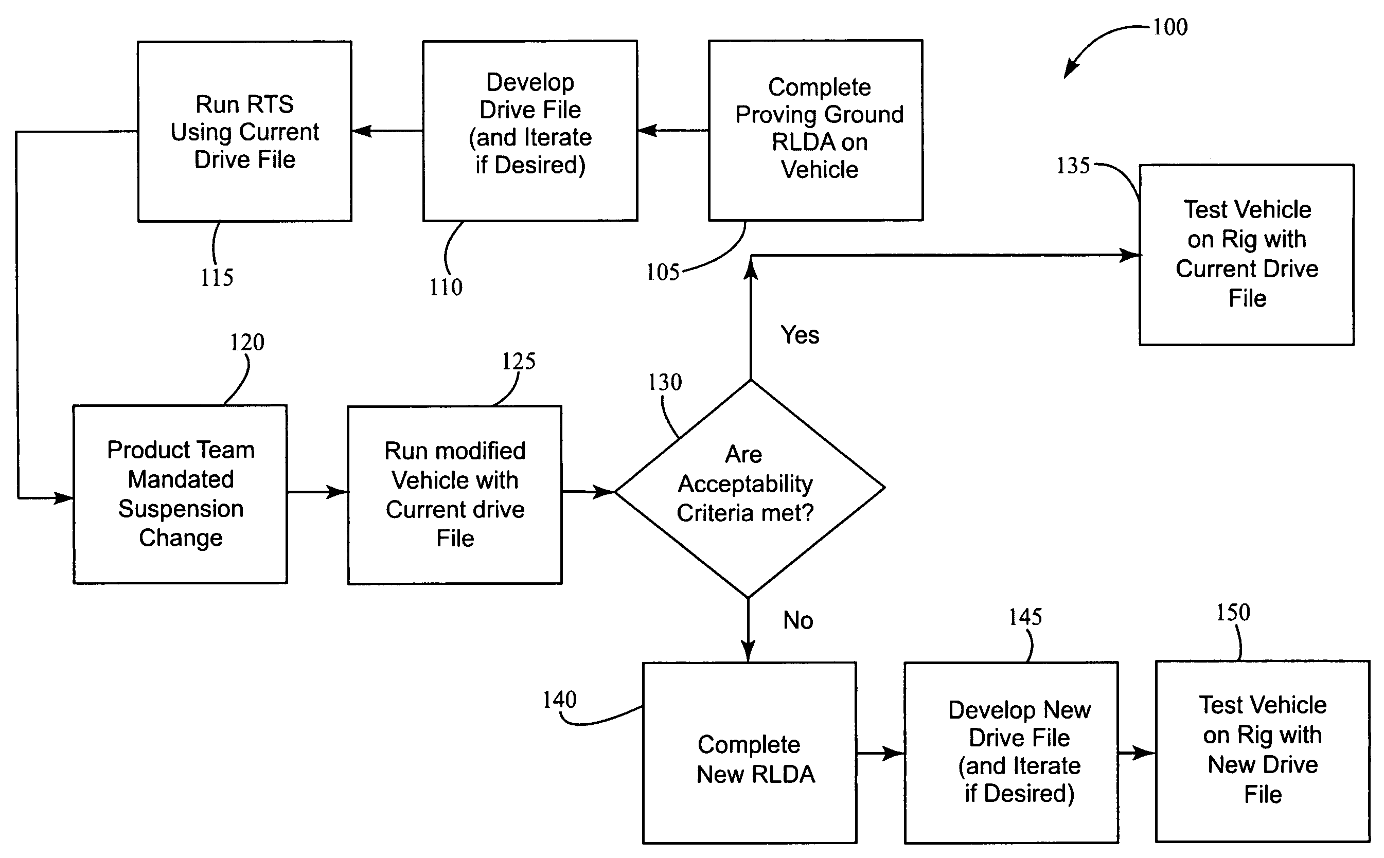
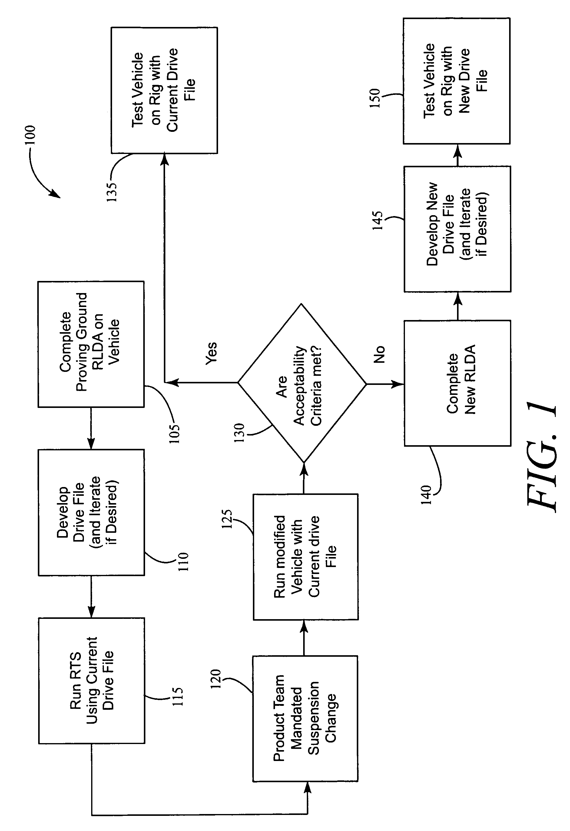
[0023]Referring in more detail to the drawings, FIG. 1 illustrates a method 100 of vehicle suspension testing. In general, vehicle development may occur over several different phases including prototype, pre-production, production, and post-production phases. During each phase, a vehicle may be tested at a proving ground to assess different aspects of vehicle performance, such as performance of a vehicle suspension and the effect of suspension performance on other aspects of the vehicle, such as suspension components and vehicle body components. The method 100 is used to assess changes in vehicle suspension parameters based on correlation between actual and simulated road test data acquisitions, and whether those changes can be reliably durability tested in a test laboratory using a road test simulation (RTS) rig without having to conduct actual road load data acquisition (RLDA) on the vehicle.

[0024]Referring in general to step 105, proving ground RLDA is carried out by completing a...


PUM


Abstract

A method of vehicle suspension testing includes conducting actual road testing of a vehicle including collecting data, and generating a drive file from the collected data for road test simulation. A vehicle suspension parameter is changed to result in a changed vehicle. Initial simulated road testing of the changed vehicle is conducted using the drive file, and results from the simulated and actual road testing are compared using acceptability criteria to determine whether to conduct further actual road testing of the changed vehicle before conducting further simulated road testing of the changed vehicle in response to the changed suspension parameter. Further simulated road testing of the changed vehicle is conducted if the acceptability criteria are met. Otherwise, further actual road testing of the changed vehicle is first conducted to develop a new drive file for use with additional simulated road testing of the changed vehicle.

Description

FIELD OF THE INVENTION[0001]The present invention relates generally to automotive durability testing, and more particularly to testing of a vehicle suspension.BACKGROUND OF THE INVENTION[0002]It is well known to test automotive vehicles for durability during various phases of vehicle development. A two-stage approach is currently used in durability testing of a vehicle suspension, and includes actual vehicle road tests at a proving ground and simulated road testing in a laboratory. In late phases of vehicle development, requests are frequently made to tune a vehicle suspension for better performance by changing various vehicle suspension parameters, like sway bar diameter or spring rate. Suspension parameter changes affect the loads on and durability of various vehicle components, and the two-stage proving ground and test rig process is typically used to assess each change. But it is time consuming and labor intensive to test the vehicles at the proving ground. Accordingly, use of t...

Claims


Application Information

Patent Timeline
Patent Type & Authority Patents(United States)
IPC IPC(8): G01M17/04
CPCG01M17/04
Inventor TEMKIN, MIKHAILVAUGHAN, RYAN ALEE, YUNG-LI
Owner FCA US
Why Eureka
Try Eureka