Inkjet recording apparatus, test image forming method, and computer-readable medium

a technology of test image and recording apparatus, which is applied in the direction of printing, other printing apparatus, etc., can solve the problems of marked decline in recording image quality, marked decline in image quality, and concerns about the decline of determination efficiency, so as to improve the reliability of the reading of the test image

Inactive Publication Date: 2009-10-01
FUJIFILM CORP +1
View PDF2 Cites 17 Cited by
  • Summary
  • Abstract
  • Description
  • Claims
  • Application Information

AI Technical Summary

Benefits of technology

[0058]According to the present invention, by setting optimal conditions of a test image through altering the X-direction and Y-direction separation intervals between a plurality of vertical lines which constitute a test image, and altering the Y-direction length of the vertical lines, on the basis of the droplet ejection pitch of the head (nozzles) and the reading pitch of the reading device, it is possible to form a test image which is little affected by positional variation of the test image caused by variation in the conveyance of the recording medium, and hence the reliability of the reading of the test image is improved and reading error can be reduced.

Problems solved by technology

However, in an inkjet recording apparatus, if an ejection abnormality occurs, such as an ejection failure in which ink is not ejected, an abnormality in the direction of flight, an abnormality in the ejection volume, or the like, then the quality of the image declines markedly.
In particular, in single-pass image forming using a full line head having nozzle rows of a length corresponding to the full width of the recording medium, if an ejection abnormality such as that described above occurs, then a white stripe following the conveyance direction arises in the recording medium and marked decline in quality occurs in the recorded image.
However, in order to judge accurately the presence or absence of an ejection abnormality for each nozzle, it is necessary to prepare a line CCD having a higher reading resolution than the print resolution, but a high-resolution line CCD requires a longer time to read in the determination signal than a low-resolution line CCD, and hence there are concerns about decline in the determination efficiency.
Furthermore, a high-resolution line CCD is expensive and is therefore unbeneficial from the viewpoint of cost.
On the other hand, if a low-resolution line CCD is used, there may be a plurality of dots in the determination area of one element and therefore it is extremely difficult to determine ejection for each respective nozzle (each dot).
If the reading resolution of the scanner unit is coarser than the printing resolution of the ejection nozzles, then a plurality of lines are read in by one determination element of the scanner unit, and as a result of this, there is a possibility that the position of a nozzle suffering ejection failure cannot be identified.
If the reading resolution of the scanner unit is not sufficiently large, then one pixel of the inspection sensor also include the next pixel of the image, and hence there is a possibility that a nozzle suffering ejection failure cannot be identified in the conveyance direction either.
In other words, if the length is insufficient in the paper conveyance direction, then this means that two patterns are read in by one determination element, and hence a nozzle suffering ejection failure cannot be identified.

Method used


Image

  • Inkjet recording apparatus, test image forming method, and computer-readable medium
  • Inkjet recording apparatus, test image forming method, and computer-readable medium
  • Inkjet recording apparatus, test image forming method, and computer-readable medium

Examples


first example

[0190]Firstly, it is confirmed that the same vertical line column 228 is not being read in by two inspection elements in the X direction. This can be done by checking for the presence of displacement in the X direction by progressively reading in the vertical lines 224 while forming the vertical line rows 226 at respectively shifted positions in the X direction.

[0191]Next, as illustrated in FIG. 12, the Y-direction length Ly of the vertical lines 224 is set to be equal to the inspection pitch in the Y direction PSY, and at least one vertical line row 226 (on region 230) and off regions 232 of the same number as the vertical line rows 226 are formed. FIG. 12 illustrates a mode where four on regions and four off regions are formed.

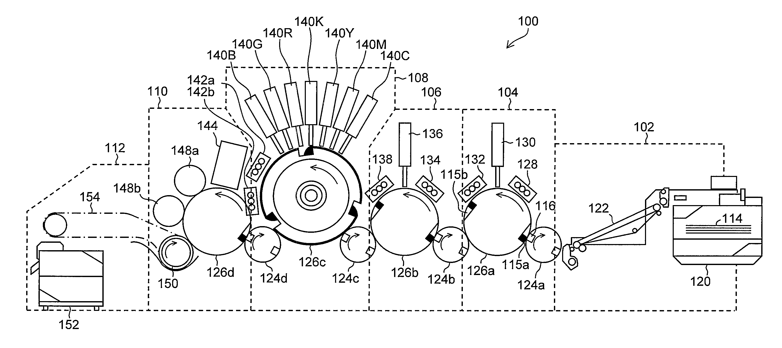
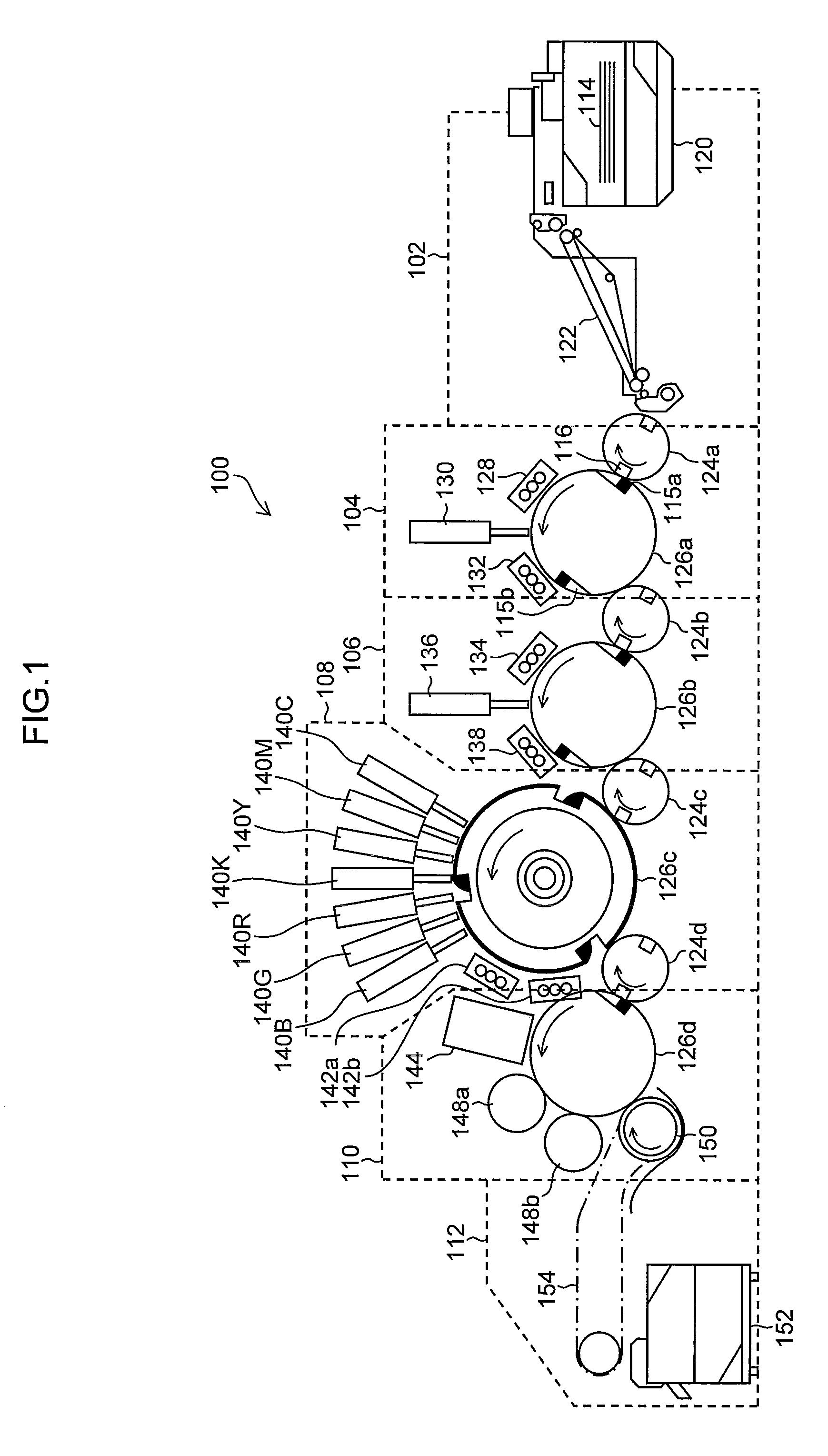
[0192]These are read in by the in-line sensor 144 (see FIG. 1), and the determination light intensity of the on regions 230 with respect to the determination light intensity of the off regions 232 (the determination light intensity ratio) is found. In other ...

second example

[0194]It is also possible to carry out the alignment described above by means of the method described below.

[0195]Droplets are ejected to create an all on pattern 240 at every other vertical column of the inspection pixels of the in-line sensor 144, this pattern 240 is determined by the in-line sensor 144, and the droplet ejection start point in the X direction is moved, one ejection dot at a time, in such a manner that the determination light intensity ratio between the on columns and off columns becomes a maximum value.

[0196]In other words, as illustrated in FIG. 13, an X-direction phase alignment test pattern 242 is formed by arranging, in two or more rows in the X direction, all on patterns 240 formed following the Y direction and each having an X-direction length of the same magnitude as the X-direction determination pitch PSX, an interval equal to the X-direction determination pitch PSX being left between the respective patterns 240.

[0197]The test pattern 242 is read in by the...


PUM


Abstract

An inkjet recording apparatus has: a head having a plurality of nozzles which eject an ink onto a recording medium; a conveyance device which conveys the recording medium; a droplet ejection control device which controls ink ejection of the head; a test image forming device that forms a test image on the recording medium by causing the ink to be ejected from every n (where n is a natural number equal to 2 or higher) nozzles in an X direction perpendicular to a direction in which the recording medium is conveyed, and causing the ink to be ejected so as to form vertical lines forming n columns which shift by one nozzle in the X direction and each extend continuously in terms of a Y direction parallel to the direction in which the recording medium is conveyed; and a reading device which is provided on a conveyance path of the recording medium, reads in a test image on the recording medium and has an image reading structure covering a length corresponding to full width of the recording medium in a breadthways direction which is perpendicular to the direction in which the recording medium is conveyed, wherein in the test image, an arrangement pitch in the X direction of the vertical lines is equal to or exceeding a reading pitch in the X direction of the reading device, an arrangement pitch in the Y direction of the vertical lines is N times a reading pitch in the Y direction of the reading device (where N is a natural number), and an interval corresponding to variation in a conveyance of the recording medium is provided between the vertical lines in such a manner that a length in the Y direction of each of the vertical lines is less than the reading pitch in the Y direction of the reading device.

Description

BACKGROUND OF THE INVENTION[0001]1. Field of the Invention[0002]The present invention relates to an inkjet recording apparatus, a test image forming method and a computer-readable medium, and more particularly to an in-line inspection and an ejection abnormality determination technology for an image determination apparatus of an inkjet recording apparatus or the like.[0003]2. Description of the Related Art[0004]Conventionally, it is suitable to use an inkjet recording apparatus as a general image forming apparatus. An inkjet recording apparatus forms a color image on a recording medium by ejecting colored inks of black, cyan, magenta, yellow, and the like, from a plurality of nozzles provided in an inkjet head. However, in an inkjet recording apparatus, if an ejection abnormality occurs, such as an ejection failure in which ink is not ejected, an abnormality in the direction of flight, an abnormality in the ejection volume, or the like, then the quality of the image declines markedl...

Claims


Application Information

Patent Timeline
Patent Type & Authority Applications(United States)
IPC IPC(8): B41J29/393
CPCB41J2/145B41J2/1721B41J29/38B41J2/185B41J2/2146B41J2/175
Inventor SAITA, HIROFUMISHIMIZU, TORU
Owner FUJIFILM CORP
Why Eureka
Try Eureka