
Enhanced electro-active lens system

a technology of electro-active lenses and enhanced lenses, which is applied in the field of enhanced electro-active lens systems, can solve the problems of affecting the perception of individuals, affecting the effect of unconventional refractive errors, and even being difficult for individuals to perceive, and fixing the effect of higher-order aberrations may still not provide an individual with proper correction

Active Publication Date: 2007-03-27
E-VISION OPTICS LLC
View PDF7 Cites 76 Cited by
  • Summary
  • Abstract
  • Description
  • Claims
  • Application Information

AI Technical Summary

Benefits of technology

[0004]Accordingly, it may be desirable to provide lens systems and optical devices that address these and other vision correction needs that permit dynamic changes in the higher order correction and / or which may assist in helping multiple persons with different higher order correction needs use the same optical device.

Problems solved by technology

Many people, even those with otherwise good vision, have minor vision deficiencies that fall under the category of non-conventional refractive error that prevent them from achieving the best visual acuity possible.
Unlike conventional refractive error, i.e. “near-sightedness” or “far-sightedness” and other types of problems usually addressed in persons with corrected vision, the impact of unconventional refractive error, such as higher order aberrations, may even be difficult for an individual to perceive until it has been identified, measured and corrected during an eye exam and the individual has an opportunity to realize the increased visual acuity that accompanies correction of these errors.
Thus, a lens that has a fixed correction for higher order aberrations may still not provide an individual a proper correction except under certain conditions.

Method used


Image

  • Enhanced electro-active lens system
  • Enhanced electro-active lens system
  • Enhanced electro-active lens system

Examples


Embodiment Construction

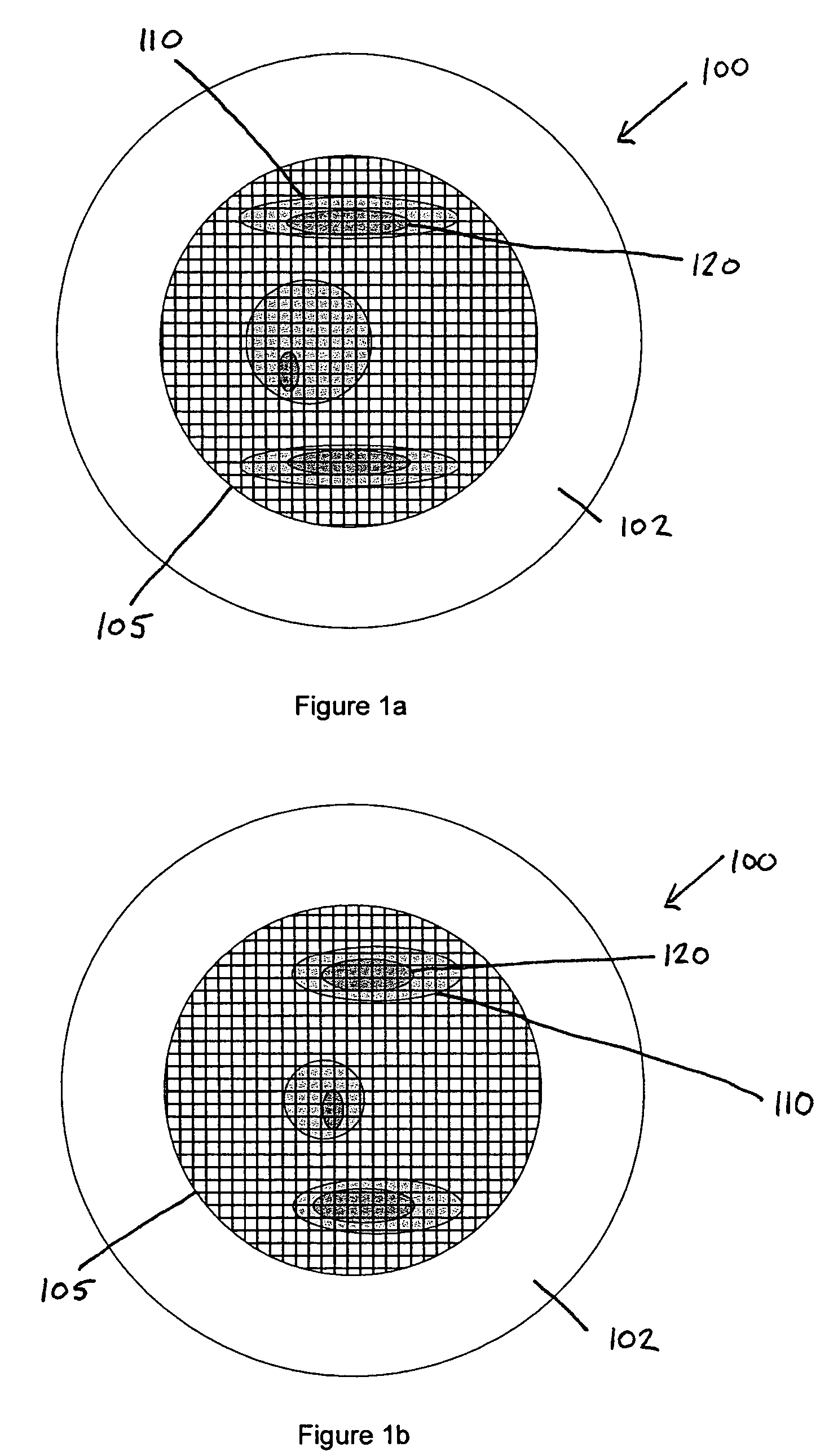
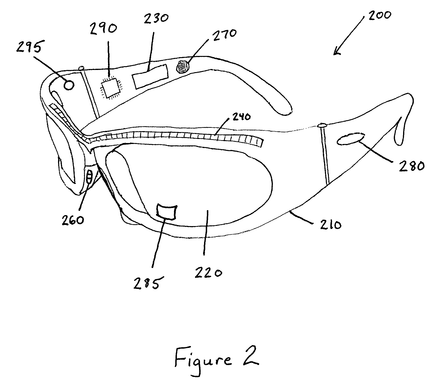
[0023]Exemplary embodiments of the invention are directed to lens systems and optical devices using lens systems that provide enhanced vision capabilities.

[0024]As described in more detail in U.S. Pat. No. 6,619,799, incorporated herein by reference in its entirety, electro-active lenses have been developed that are capable of providing vision correction that corrects for both conventional refractive error, such as hyperopia and myopia, and that corrects for non-conventional refractive error, including higher order aberrations.

[0025]The benefits of correcting non-conventional refractive error in particular may provide an individual with a visual acuity that is better than 20 / 20. Non-conventional errors, particularly higher order aberrations, such as coma, for example, typically result from deficiencies within the eye and often prevent even those with good vision, i.e. 20 / 20, from improving visual acuity to a higher level such as 20 / 15, 20 / 10 or even approaching 20 / 8.

[0026]The effect...


PUM


Abstract

A lens system and optical devices that provide enhanced vision correction are disclosed. The lens system includes an electro-active layer that provides correction of at least one higher order aberration. The higher order correction changes dynamically based on a user of the lens system's needs, such as a change by the user's gaze distance, pupil size, or changes in tear film following blinking, among others. Optical devices are also described that use these and other lens systems to provide correction of higher order aberrations. An optical guide is also described that guides the user's line of sight to see through a lens region having a correction for a higher order aberration.

Description

RELATED APPLICATIONS[0001]The present application claims priority to U.S. Provisional Application No. 60 / 495,110, filed Aug. 15, 2003; 60 / 502,630, filed Sep. 15, 2003; 60 / 511,128, filed Oct. 15, 2003; 60 / 523,674, filed Nov. 21, 2003; 60 / 544,964 filed Feb. 17, 2004, 60 / 552,198, filed Mar. 12, 2004, and 60 / 566,406 filed Apr. 30, 2004. All of the foregoing applications are hereby incorporated by reference in their entirety.BACKGROUND OF THE INVENTION[0002]Many people, even those with otherwise good vision, have minor vision deficiencies that fall under the category of non-conventional refractive error that prevent them from achieving the best visual acuity possible. Unlike conventional refractive error, i.e. “near-sightedness” or “far-sightedness” and other types of problems usually addressed in persons with corrected vision, the impact of unconventional refractive error, such as higher order aberrations, may even be difficult for an individual to perceive until it has been identified,...

Claims


Application Information

Patent Timeline
Patent Type & Authority Patents(United States)
IPC IPC(8): G02C7/02G02B26/06G02C7/10G02C7/12
CPCG02B26/06G02C7/083G02C7/088G02B27/0172G02B2027/0123G02B2027/0178G02B2027/011G02C2202/22G02B26/00G02B27/01G02C7/02G02C7/12
Inventor BLUM, RONALD D.KOKONASKI, WILLIAMDUSTON, DWIGHT P.
Owner E-VISION OPTICS LLC
Learn More