Compliant mounting system for turbine shrouds

a technology for mounting systems and turbines, which is applied in the direction of liquid fuel engines, forging/pressing/hammering apparatus, lighting and heating apparatus, etc., can solve the problems of reducing the efficiency of compressors or turbines, loose shrouds, and large gap between tip and tip,

Inactive Publication Date: 2007-03-27
HONEYWELL INT INC
View PDF25 Cites 43 Cited by
  • Summary
  • Abstract
  • Description
  • Claims
  • Application Information

AI Technical Summary

Problems solved by technology

Blade tip clearances or clearance gaps that are too large reduce the efficiency of the compressor or turbine while clearances which are too small may cause damage under some conditions due to interference between the blade tips and the shroud ring.
This generates stress and distortion in the shroud that is not desirable and may result in larger than desired tip gaps to prevent the blade tips from contacting the shroud.
These clearances result in the shroud being loose in the case when assembled and reduces the ability to align the shroud to the center of blade tip rotation.
By using a single spring of uniform stiffness, however, pins may be required to provide a positive stop, which, in many cases, may not provide the needed positioning control.
While these flats may impart local radial forces at three locations during a shroud rub, these forces may be insufficient to fully prevent rotation in the event of a shroud rub at higher shroud torque loads.
These plates may need to be slotted and cooled to prevent distortion and burning, resulting in additional machining time and expense.

Method used


Image

  • Compliant mounting system for turbine shrouds
  • Compliant mounting system for turbine shrouds
  • Compliant mounting system for turbine shrouds

Examples


Embodiment Construction

[0021]The following detailed description is of the best currently contemplated modes of carrying out the invention. The description is not to be taken in a limiting sense, but is made merely for the purpose of illustrating the general principles of the invention, since the scope of the invention is best defined by the appended claims.

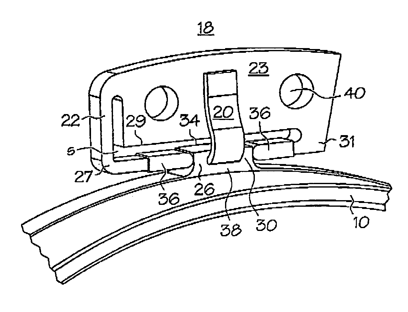
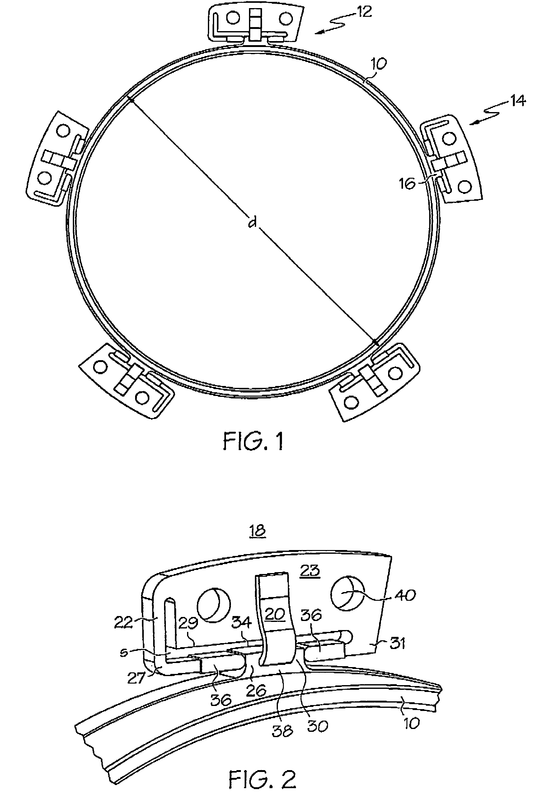
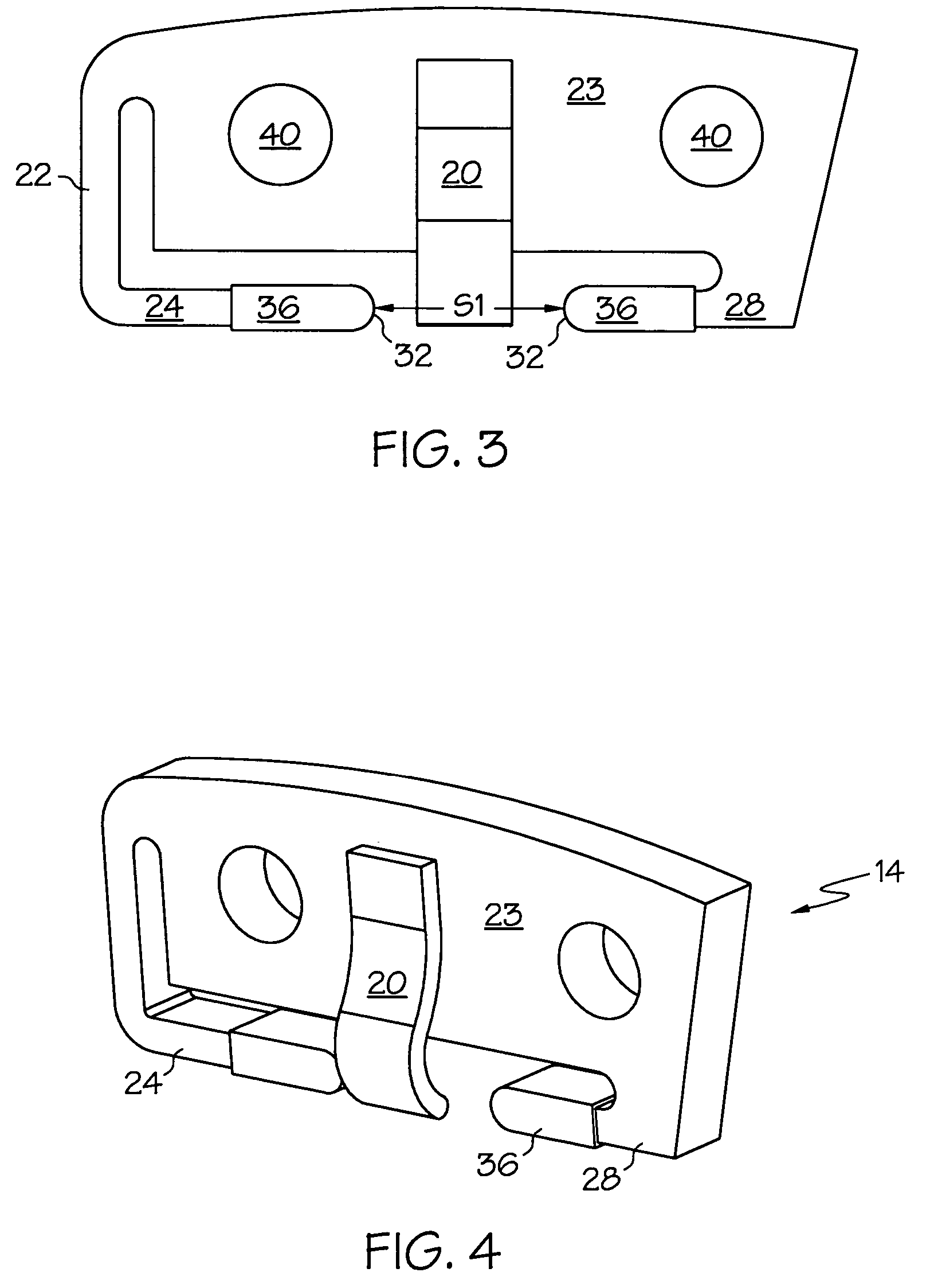
[0022]Broadly, the present invention provides a compliant mounting system for a component, such as a turbine shroud, and a method for mounting a component, such as a turbine shroud onto a second component, such as a gas turbine engine. The mounting of full ring shrouds in a turbine engine requires radial compliance to limit the stresses experienced by the shroud due to thermal growth differences between the shroud and its support. In commonly used mounting systems, positional uncertainty, or looseness, due to dimensional tolerances required to assemble the shroud may result in additional tip clearances and thus lower engine performance. Unlike conventio...


PUM

PropertyMeasurementUnit
diameteraaaaaaaaaa
resilient forceaaaaaaaaaa
actuate shapeaaaaaaaaaa

Abstract

The mounting of low expansion full ring shrouds in a turbine engine requires radial compliance to limit the stresses experienced by the shroud due to thermal growth differences between the shroud and its support. A method provides radial compliance with no looseness in a mounting system. The mounting system also allows for axial motion of the shroud, should such motion be needed or desired. The lack of looseness in the mounting system results in an ability to achieve smaller tip clearances and thus better engine performance.

Description

GOVERNMENT RIGHTS[0001]This invention was made with Government support under Contract Number DAAH10-03-2-0007 awarded by the United States Army. The Government has certain rights in this invention.BACKGROUND OF THE INVENTION[0002]The present invention generally relates to a mounting system for a turbine shroud and, more specifically, to a mounting system for a turbine shroud that provides radial compliance while minimizing looseness in the mounting system. The present invention also relates to methods for mounting a turbine shroud in a gas turbine engine.[0003]Axial flow compressor or turbine rotor blade stages in gas turbine engines may be provided with shroud rings for the purpose of maintaining clearances between the tips of the rotor blades and the shrouds over as wide a range of rotor speeds and temperatures as possible. Blade tip clearances or clearance gaps that are too large reduce the efficiency of the compressor or turbine while clearances which are too small may cause dam...

Claims


Application Information

Patent Timeline
Patent Type & Authority Patents(United States)
IPC IPC(8): F01D11/08F01D25/26
CPCF01D9/02F01D25/246F01D25/26Y10T29/49323Y10T29/4932Y10T29/49874Y10T29/49863F05D2240/11
Inventor ALLAN, ADRIAN R.HADDER, JAMES L.ZURMEHLY, GEORGE E.
Owner HONEYWELL INT INC
Why Eureka
Try Eureka