
Connector assembly

Active Publication Date: 2007-03-27
OYO GEOSPACE CORP
View PDF14 Cites 79 Cited by
  • Summary
  • Abstract
  • Description
  • Claims
  • Application Information

AI Technical Summary

Benefits of technology

[0018]Another object of the invention is to provide a connector pair with redundant seals which minimize the force required to mate the connectors.
[0019]Another object of the invention is to provide a connector pair which minimize the potential for bending or breaking contacts during the mating process.SUMMARY OF THE INVENTION

Problems solved by technology

However, sealing the interface between two mated connectors has traditionally been limited to the use of gaskets or O-rings which are compressed so that they conform to adjacent surfaces, thereby creating a fluid-proof barrier or seal which can be repeatedly mated and unmated.
A connector pair having only one interface sealing element provides no sealing redundancy, so that a defective seal at the connector interface is likely to destroy the integrity of the connection.
Because it requires more force to move one connector relative to other when a sealing element is significantly compressed therebetween, it is more difficult for one to mate the connector pair.
Hence, operators become accustomed to applying a greater force to mate redundantly-sealed connectors then is customary for mating single-seal connectors, thereby increasing the likelihood of damaging one or more contact pins.
If the connectors are initially misaligned, then the operator may not tactilely recognize the misalignment and instead apply too great a force, in turn bending one or more pins.
Furthermore, with the prior art connector pair of FIG. 1, it is more difficult for the operator to tactilely feel if both sealing elements have engaged or whether only one sealing element has engaged.

Method used


Image

  • Connector assembly
  • Connector assembly
  • Connector assembly

Examples


Embodiment Construction

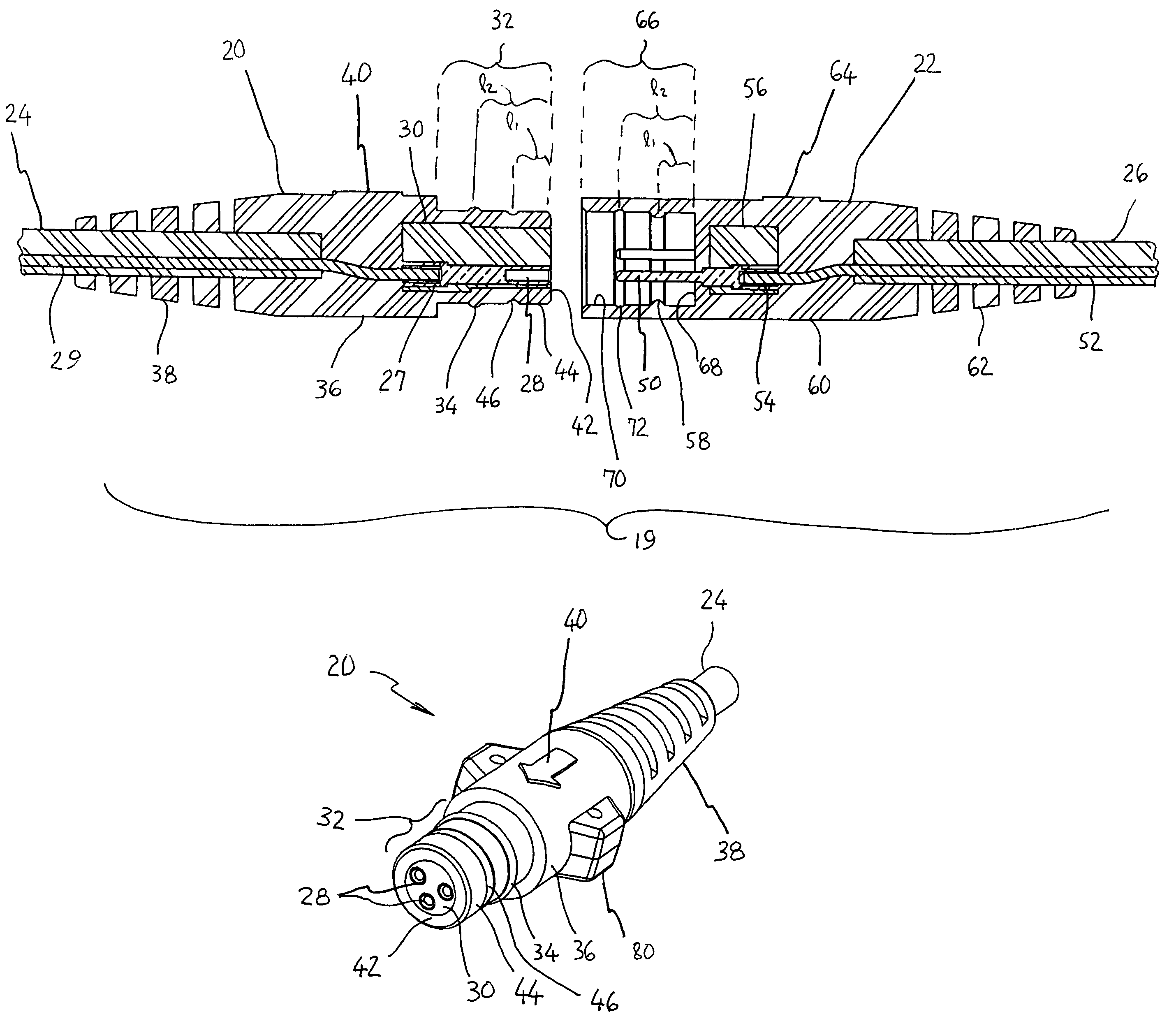
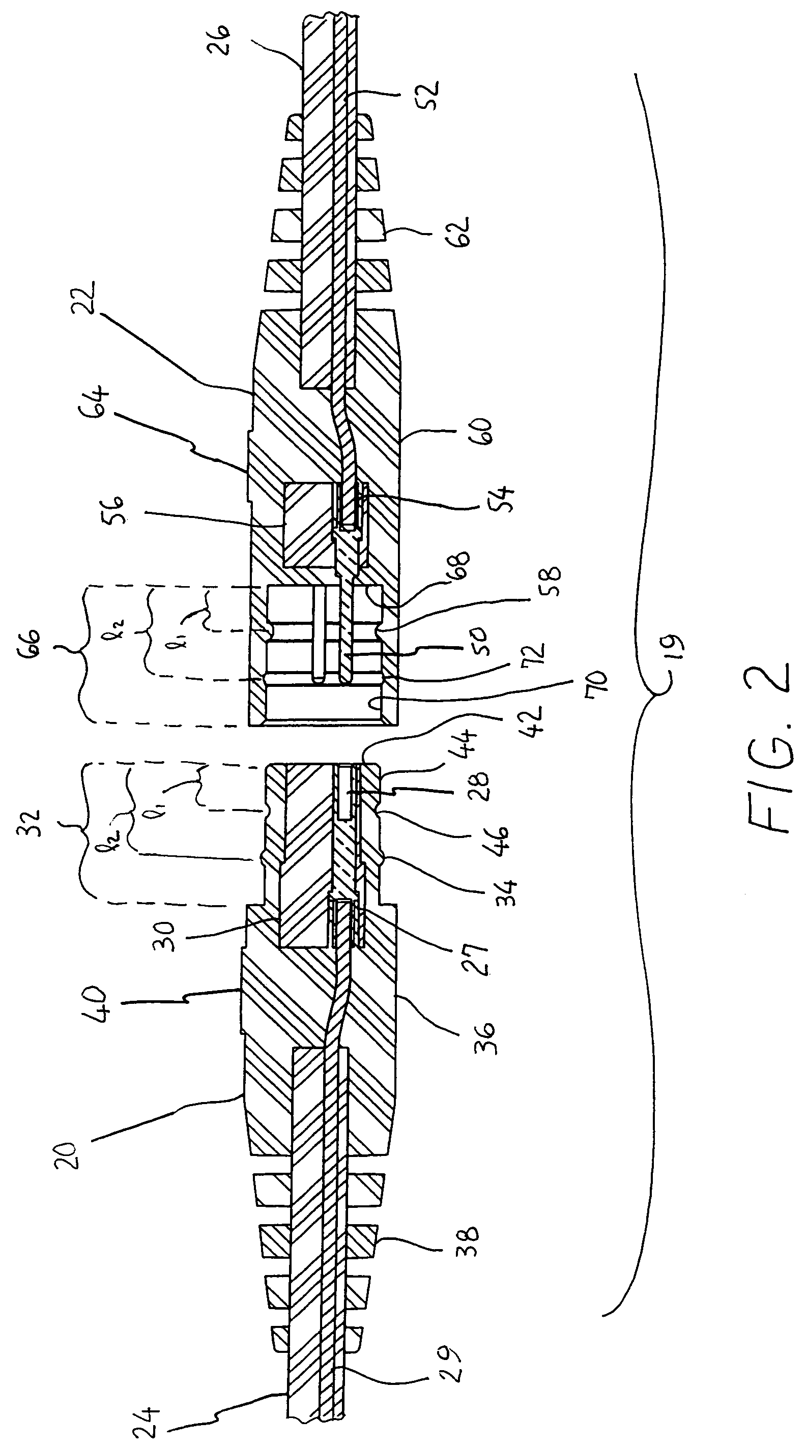
[0028]FIG. 2 depicts a connector pair 19 according to a first embodiment of the invention. The connector pair includes a male connector 20 which terminates cable 24 and a female connector 22 which terminates cable 26. The male connector 20 is designed and arranged to couple with the female connector 22.

[0029]The male connector 20 preferably includes contact sockets 28 that are electrically connected to conductors 29 in cable 24 (and / or optically connected to optical fibers in cable 24). However, contact pins, blades, spades, or similar devices may be used in place of or in addition to contact sockets as appropriate. For electrical connections, the conductors 29 are typically crimped within or soldered to tailpiece portions 70 of the contacts 28, although other suitable termination methods may be used. Any number of contacts 28 may be included as required for the application.

[0030]The contact sockets 28 are preferably seated in an insert 30 which holds the contact sockets 28 in posit...


PUM


Abstract

An apparatus for producing a watertight connection for the purpose of joining electrical or optical circuits including, in a preferred embodiment, a male connector with a cylindrical plug characterized by having a first groove and a first raised seal disposed about the plug's outer side surface and a female connector with a cylindrical receptacle characterized by a second groove and a second raised seal disposed about receptacle's inner side surface, such that the seal of the plug is received in the groove of the receptacle, and groove of the plug receives the seal of the receptacle, thereby operatively coupling the contacts in a redundantly sealed environment. The first and second grooves are disposed distal to the raised seals (with respect the cable end of the connectors) so that when the connector pair is mated, the grooves pass each other without interference and the seals simultaneously engage the grooves.

Description

CROSS REFERENCE TO RELATED APPLICATION[0001]This application is based upon provisional application 60 / 625,833 filed on Nov. 8, 2004, the priority of which is claimed.BACKGROUND OF THE INVENTION[0002]1. Field of the Invention[0003]This invention relates generally to the field of electrical or fiber-optic connectors possessing moisture and water proof integrity. More specifically, this application relates to connectors with additional features that facilitate ease of orientation and mating and result in a redundant seal.[0004]2. Description of the Prior Art[0005]As a preface, it should be noted that “male” and “female” designations for electrical connectors are not used consistently in the field. Some connectors are designated as “male” because their inserts are received into the shells of the mating connectors, regardless of whether their electrical contacts are sockets, pins (or blades, etc.), or a combination of sockets and pins. (“Insert,” as used herein, designates that part of t...

Claims


Application Information

Patent Timeline
IPC IPC(8): H01R13/52
CPCH01R13/5219H01R13/6271H01R13/562
Inventor BECKER, TIMOTHY D.
Owner OYO GEOSPACE CORP
Features
  • Generate Ideas
  • Intellectual Property
  • Life Sciences
  • Materials
  • Tech Scout
  • Unparalleled Data Quality
  • Higher Quality Content
  • 60% Fewer Hallucinations
Learn More