Method and apparatus for fixing a graft in a bone tunnel

a bone tunnel and graft technology, applied in the field of surgical methods and equipment, can solve problems such as partial or permanent disability

Inactive Publication Date: 2007-03-27
DEPUY SYNTHES PROD INC
View PDF27 Cites 32 Cited by
  • Summary
  • Abstract
  • Description
  • Claims
  • Application Information

AI Technical Summary

Problems solved by technology

If, however, the ligament or tendon is completely detached from its associated bone or bones, or if it is severed as the result of a traumatic injury, partial or permanent disability may result.
However, the femoral cross-pinning methods and apparatus that are presently known in the art do not address the use of a cross-pin in a tibial bone tunnel, which involves a different set of considerations.

Method used


Image

  • Method and apparatus for fixing a graft in a bone tunnel
  • Method and apparatus for fixing a graft in a bone tunnel
  • Method and apparatus for fixing a graft in a bone tunnel

Examples


Embodiment Construction

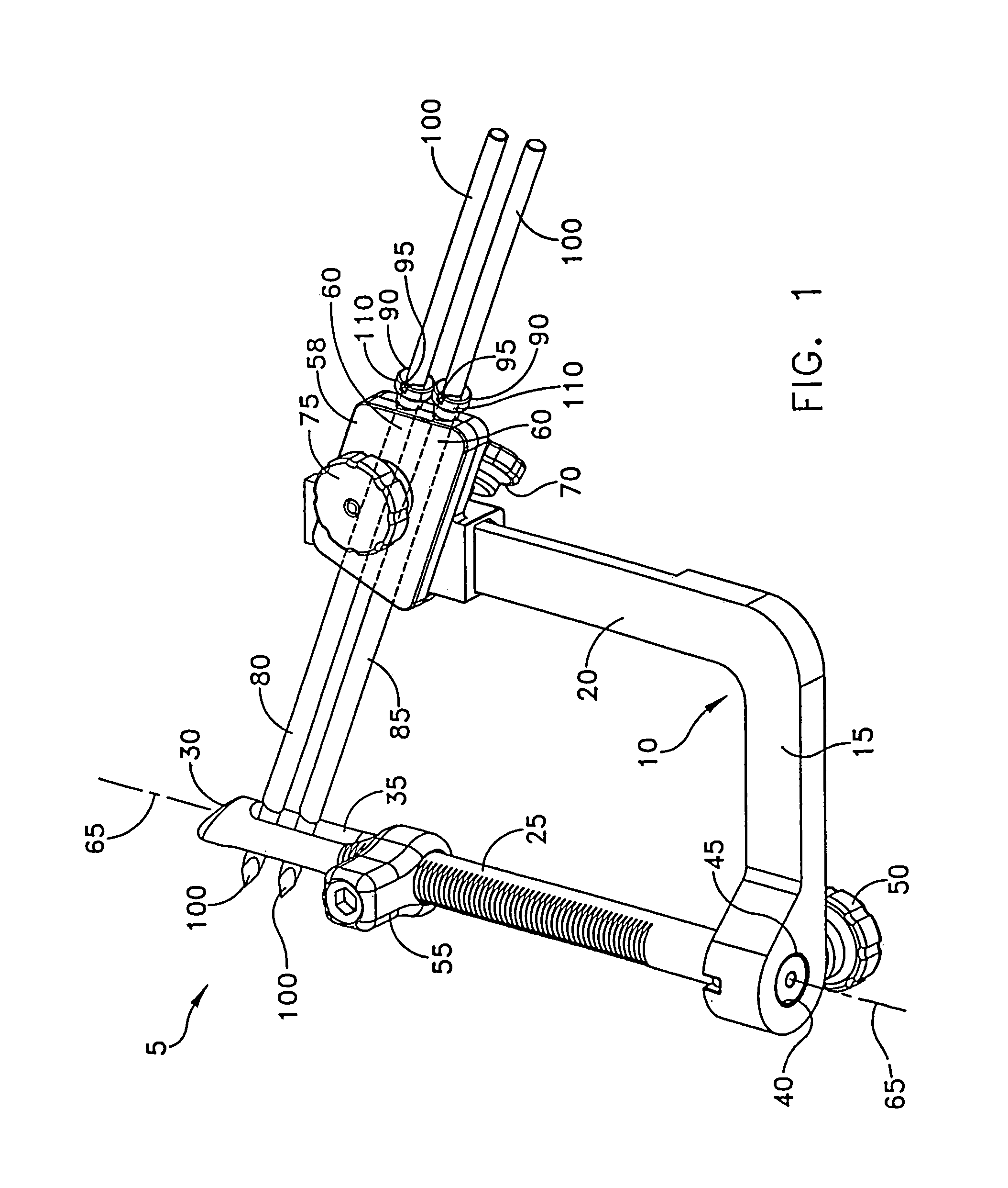
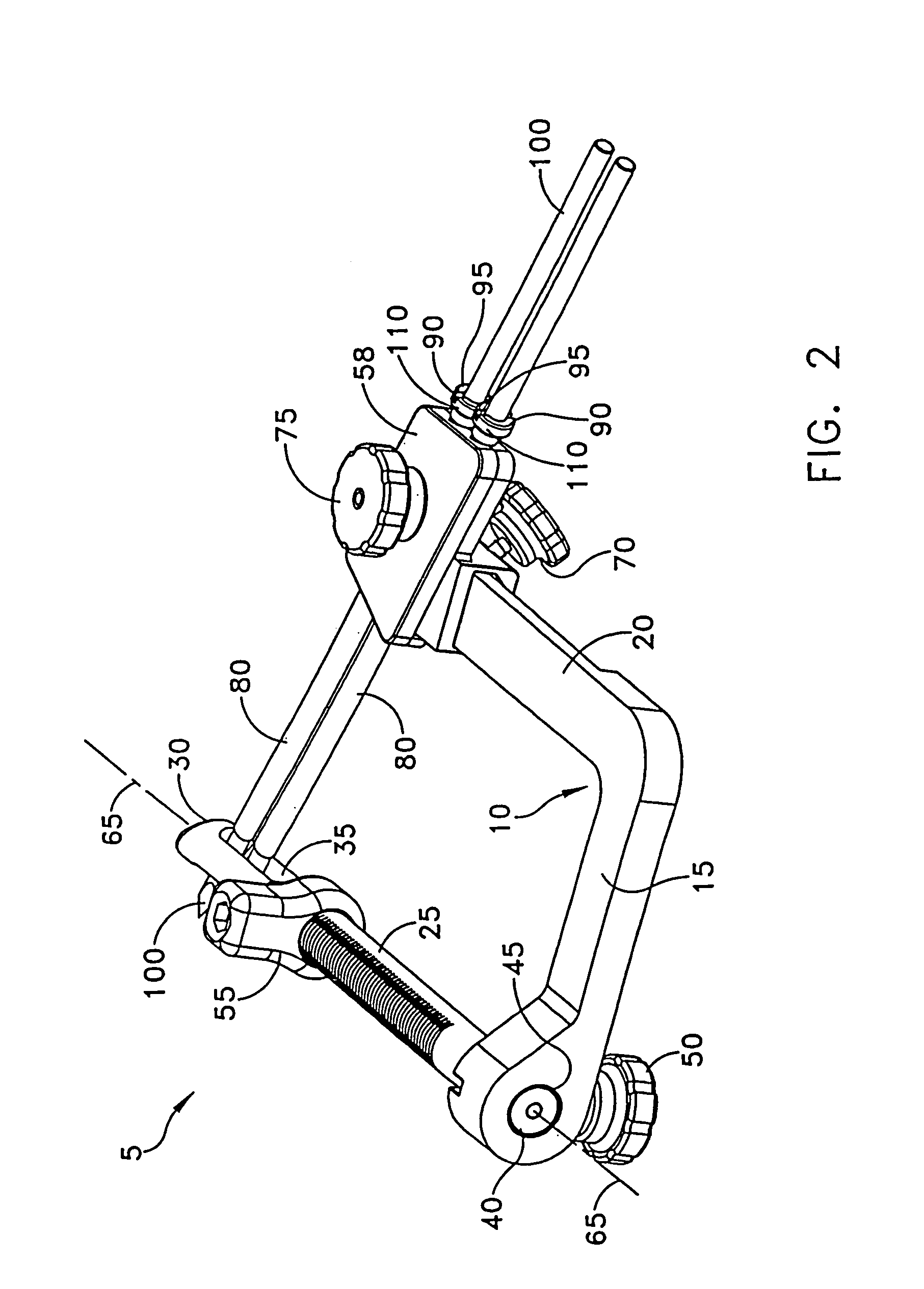
[0039]Looking first at FIGS. 1–10, there is shown a cross-pin guide assembly 5 for placement of at least one cross-pin (not shown in FIGS. 1–10) in a bone tunnel, such as the tibial tunnel of a knee joint. Cross-pin guide assembly 5 comprises an L-shaped member 10 having a base portion 15 and an arm portion 20. The arm portion 20 extends transversely to, and preferably is normal to, base portion 15.

[0040]Cross-pin guide assembly 5 further comprises a bone tunnel guide rod 25 which, adjacent to a first end 30 thereof, forms a diametrical, longitudinally-elongated passageway 35, and which, at a second end 40 thereof, is releasably connectable to base portion 15 of L-shaped member 10. In a preferred embodiment, bone tunnel guide rod 25 is cannulated along its axis 65 (see FIGS. 1–10) for placement on a guidewire (not shown in FIGS. 1–10). Bone tunnel guide rod 25 may be retained in a bore 45 formed in base portion 15 by a set screw 50. In an alternative embodiment, bone tunnel guide ro...


PUM


Abstract

A graft ligament for cross-pinning in a bone tunnel, the ligament comprising a tendon having first, second and third portions in series along the length thereof. The first and third portions are provided with cross-sectional thicknesses less than the cross-sectional thickness of the second portion. The tendon first and third portions are folded over and attached to the second portion to provide a graft ligament having a substantially uniform thickness along the length thereof.

Description

REFERENCE TO PENDING PRIOR PATENT APPLICATION[0001]This patent application claims benefit of pending prior U.S. Provisional Patent Application Ser. No. 60 / 275,431, filed Mar. 13, 2001 by Gregory Whittaker for METHOD AND APPARATUS FOR FIXING A GRAFT IN A TIBIAL TUNNEL (Attorney's Docket No. MIT-ZZ PROV), which patent application is hereby incorporated herein by reference.FIELD OF THE INVENTION[0002]This invention relates to surgical methods and apparatus in general, and more particularly to methods and apparatus for fixing a graft in a bone tunnel.BACKGROUND OF THE INVENTION[0003]The complete or partial detachment of ligaments, tendons and / or other soft tissues from their associated bones within the body are relatively commonplace injuries. Tissue detachment may occur as the result of an accident such as a fall, overexertion during a work-related activity, during the course of an athletic event, or in any one of many other situations and / or activities. Such injuries are generally the...

Claims


Application Information

Patent Timeline
Patent Type & Authority Patents(United States)
IPC IPC(8): A61F2/02A61B17/56A61B17/16A61B17/17A61B17/58A61B19/00A61F2/08
CPCA61B17/1714A61B17/1764A61F2/0805A61F2/0811A61F2/08A61B17/1637A61B17/1675A61B2019/304A61B2019/462A61F2002/087A61F2002/0882A61B2090/034A61B2090/062
Inventor MCKERNAN, DANIEL J.WHITTAKER, GREGORY R.
Owner DEPUY SYNTHES PROD INC
Why Eureka
Try Eureka