Apparatus and method for reconstructing a ligament

Inactive Publication Date: 2006-06-20
ENTERPRISES HLDG INC
View PDF31 Cites 66 Cited by
  • Summary
  • Abstract
  • Description
  • Claims
  • Application Information

AI Technical Summary

Benefits of technology

[0014]In one preferred method of use, a graft ligament is looped through the graft hole in the graft ligament support block, and the graft ligament support block is mounted to the installation tool. The two free ends of the graft ligament are then preferably secured to a proximal portion of the installation tool under tension, whereby to tie down the two free ends of the graft ligament. In addition to controlling the two free ends of the graft ligament, this arrangement will also help hold the graft ligament support block to the installation tool. Then the installation tool is used to advance the graft ligament support block through the tibial tunnel, across the interior of the knee joint, and up into the femoral tunnel, with the two free ends of the looped graft ligament extending back out through the tibial tunnel. Next, a transverse tunnel is formed in

Problems solved by technology

Ligaments are frequently damaged (e.g., detached or torn or ruptured, etc.) as the result of injury and/or accident.
A damaged ligament can cause instability, impede proper motion of a joint and cause pain.
A damaged ACL can cause instability of the knee joint and cause substantial pain and arthritis.
However, this procedure is also generally considered to be highly invasive and, in many cases, quite painful, and typically leaves unsightly scarring on the knee and a substantial void in the knee cap.
However, soft tissue grafts such as the hamstring can be difficult to stabilize within a bone tunnel.
More particularly, the use of an interference screw to aggressively wedge the hamstring against an opposing side wall of the bone tunnel can introduce issues such as graft slippage, tendon winding, tissue necrosis and tendon cutting.
Furthermore, the use of a

Method used


Image

  • Apparatus and method for reconstructing a ligament
  • Apparatus and method for reconstructing a ligament
  • Apparatus and method for reconstructing a ligament

Examples


Embodiment Construction

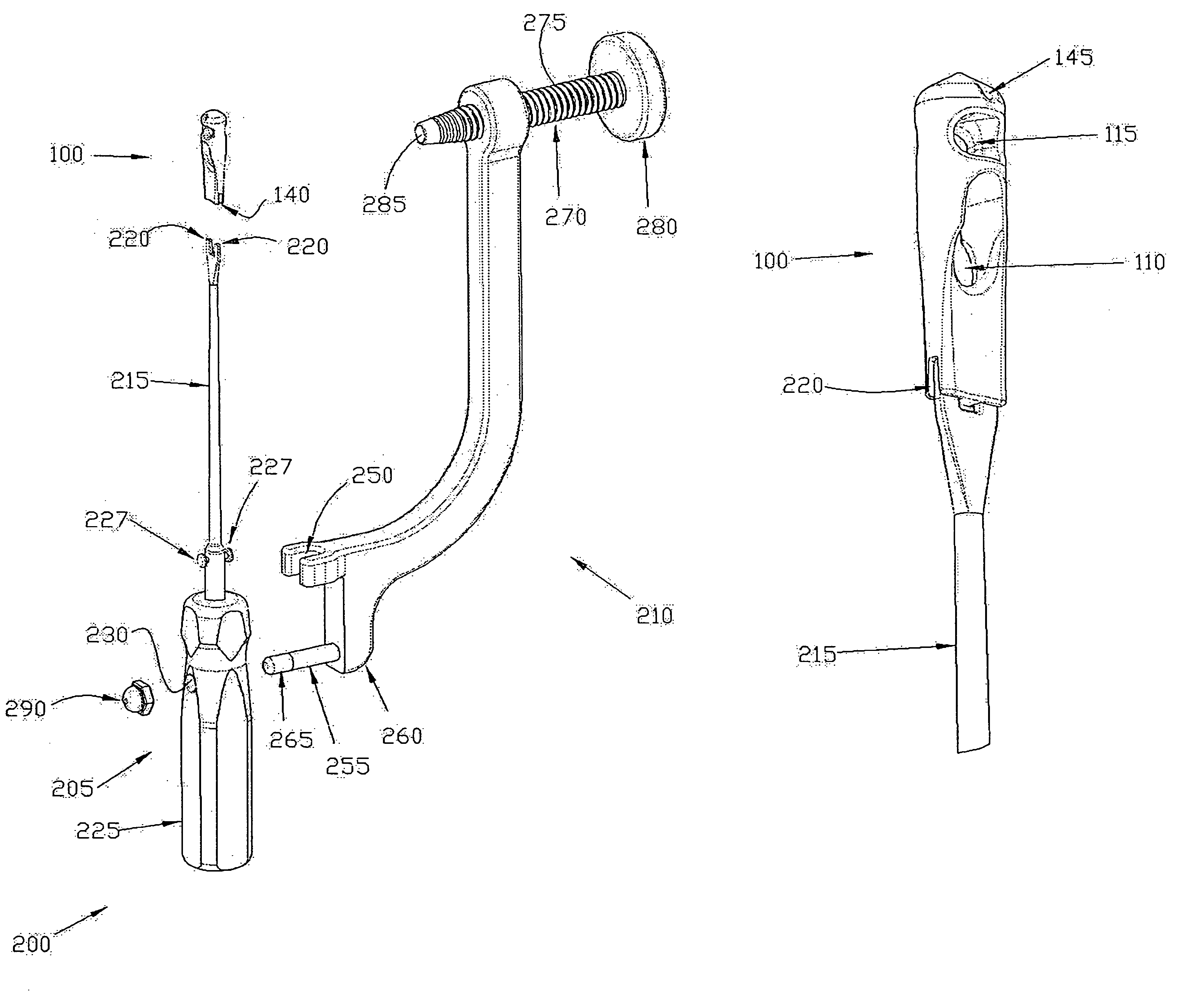
[0037]Looking next at FIG. 8, there is shown a graft ligament support block 100 which comprises one preferred form of the invention. Graft ligament support block 100 comprises a body 105, and a graft hole 110 and a transverse fixation pin hole 115 extending through body 105, with both graft hole 110 and transverse fixation pin hole 115 preferably extending substantially perpendicular to the longitudinal axis 120 of body 105. In one preferred form of the invention, graft hole 110 and transverse fixation pin hole 115 extend diametrically across body 105, with graft hole 110 and transverse fixation pin hole 115 extending substantially parallel to one another. Preferably graft hole 110 resides closer to the proximal end 125 of body 105 than transverse fixation pin hole 115, and transverse fixation pin hole 115 resides closer to the distal end 130 of body 105 than graft hole 110. In one preferred form of the invention, the distal end of body 105 has a circular cross-section, although it ...


PUM


Abstract

Method and apparatus for reconstructing a ligament. A graft ligament support block comprises a body, a graft hole, and a transverse fixation pin hole extending through the body. An installation tool is provided for inserting the support block into a bone tunnel and forming a transverse tunnel aligned with the pin hole. In use, a graft ligament is looped through the graft hole, and the support block is mounted to the tool. The tool is used to advance the support block into the bone tunnel, with two free ends of the graft ligament extending out the bone tunnel. A transverse tunnel is formed aligned with the pin hole. The support block is secured in place by pinning the support block within the tunnel by advancing a fixation pin along the transverse tunnel and into the pin hole in the support block.

Description

REFERENCE TO PENDING PRIOR PATENT APPLICATIONS[0001]This is a continuation of prior U.S. patent application Ser. No. 10 / 123,434, filed Apr. 16, 2002 now U.S. Pat. No. 6,712,849 by Paul Re et al. for APPARATUS AND METHOD FOR RECONSTRUCTING A LIGAMENT, which in turn claims benefit of pending prior U.S. Provisional Patent Application Ser. No. 60 / 326,351, filed Oct. 1, 2001 by Paul Re et al. for APPARATUS AND METHOD FOR RECONSTRUCTING A LIGAMENT. The above-identified patent applications are hereby incorporated herein by reference.FIELD OF THE INVENTION[0002]This invention relates to surgical apparatus and procedures in general, and more particularly to surgical apparatus and procedures for reconstructing a ligament.BACKGROUND OF THE INVENTION[0003]A ligament is a piece of fibrous tissue which connects one bone to another.[0004]Ligaments are frequently damaged (e.g., detached or torn or ruptured, etc.) as the result of injury and / or accident. A damaged ligament can cause instability, imp...

Claims


Application Information

Patent Timeline
IPC IPC(8): A61F2/08A61B17/56A61B17/16A61B17/17A61B19/00
CPCA61B17/1714A61F2/0805A61F2/0811A61B17/1764A61B17/1675A61B2019/462A61F2002/0829Y10S606/909A61F2002/0882Y10S606/907Y10S606/916Y10S606/908Y10S606/91A61F2002/0852A61B2090/062
Inventor RE, PAULJOHANSON, MARK A.MARSHALL, PETER F.
Owner ENTERPRISES HLDG INC
Why Eureka
Try Eureka