Method and apparatus for reconstructing a ligament

a ligament and surgical method technology, applied in the field of surgical methods and equipment, can solve the problems of not being able to fully determine the extent, timing and type of ingrowth occurring on the screw side of the tendon, and not being able to achieve bony ingrowth, and achieve stable fixation, stable aperture fixation, and enhanced fixation

Inactive Publication Date: 2005-06-23
KARL STORZ GMBH & CO KG
View PDF8 Cites 70 Cited by
  • Summary
  • Abstract
  • Description
  • Claims
  • Application Information

AI Technical Summary

Benefits of technology

[0021] When used with tendon grafts with attached bone blocks, such as bone-patella tendon-bone (BPTB) grafts, fixation will also be enhanced by “locking” the bone block deep in the bone tunnel, deep to the bone wedge layer that has been compressed into the graft by the interference device. When using either soft tissue grafts or grafts with attached bone blocks, stable fixation at the aperture of the bone tunnel, necessary to minimize the previously described motion of the tendon within the tunnel, is provided.
[0022] This new approach also helps solve the problem of providing aperture fixation when using BPTB grafts. More particularly, the tendinous portions of these grafts are usually longer than the normal intra-articular length of the native cruciate ligament. As a result, reconstruction using a BPTB graft usually requires that the bone plug either be fixed deep in the bone tunnel, making aperture fixation impossible, or the bone plug on one end of the tendon must be doubled back on itself prior to graft passage, which presents technical difficulties. The new approach presented here provides fixation of the tendon block deep in the bone tunnel while also providing stable aperture fixation.
[0023] Significantly, the foregoing new fixation technique retains the established benefits of the interference fixation techniques currently widely utilized in ligament reconstruction. At the same time, creation of an intervening layer of bone to provide circumferential bone / tendon graft contact significantly enhances the potential for bone ingrowth into the tendon graft, which is important for clinically successful results.
[0024] A fixation device specific for this technique may enhance the benefits of the new approach described above. Several different device designs are possible. One such device is essentially a combination of a screw and pin. The screw portion, essentially similar to an interference screw, enables introduction of the implant while providing compression fixation. The modified tip of the device, of which several configurations are possible, is designed to enhance fixation strength by providing a combination of oblique interstitial transfixation and compression of the end of the tendon graft deep in the bone tunnel.

Problems solved by technology

With interference screw fixation this ingrowth is possible only on the side of the graft that is in direct contact with bone; the other half of the graft contacts only the screw and hence is not available for bony ingrowth.
However, the timing, extent and type of ingrowth occurring on the screw side of the tendon, after the bioresorbable screw has been resorbed, has yet to be fully determined.
In addition to the foregoing, spinning of the tendon graft during insertion of the interference screw is a well-documented problem that is difficult to control once it has begun.
This “tendon spin” can damage the graft and result in impingement and less-than-ideal graft positioning, possibly affecting the clinical results.
However, such distal types of fixation are often less stiff and provide less stable fixation of the graft in the bone tunnel.
This decreased stability and subsequent increased graft-tunnel motion may inhibit the formation of a stable graft-bone interface, interfering with graft incorporation into the adjacent bone and the creation of a functionally stable ligament reconstruction.
In addition, this increased graft motion has been associated with widening of the bone tunnel.

Method used


Image

  • Method and apparatus for reconstructing a ligament
  • Method and apparatus for reconstructing a ligament
  • Method and apparatus for reconstructing a ligament

Examples


Embodiment Construction

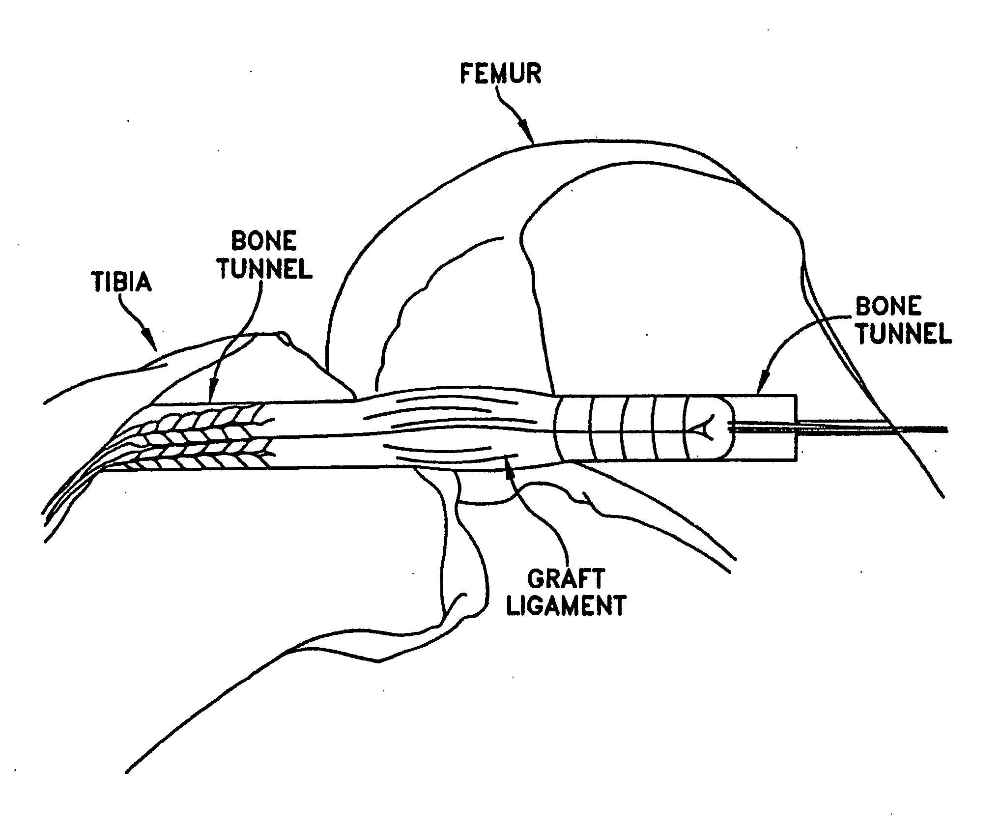
[0051] This detailed description will again use the femoral side of an ACL reconstruction as an example of the multiple uses of this new concept; however, as noted above, this application is intended to be merely exemplary and the invention may be used on the tibial side of an ACL reconstruction, or in connection with some other type of ligament reconstruction, etc.

[0052] Using this new approach, the initial steps in the ACL reconstruction are unchanged from that usually done when using interference screws for graft fixation. Autografts or allografts, with or without attached bone blocks, can be utilized. Arthroscopic examination of the knee is done in the standard fashion, with debridement of the residual anterior cruciate ligament tissue and preparation of the femoral notch. The tendon graft is harvested, prepared, and measured. The bone tunnels are made in the tibia and femur in the standard fashion, typically using one of the commercially available guidance systems. As always, ...


PUM


Abstract

A new approach for reconstructing a ligament, the new approach comprising: creating a bone tunnel within a host bone, the bone tunnel having a proximal end and a distal end, and defining a central axis extending from the proximal end to the distal end; creating an intervening layer of bone between the central axis of the bone tunnel and a rigid portion of the host bone, the intervening layer having a first side and a second side in opposition to one another, the first side of the intervening layer facing toward the central axis of the bone tunnel and the second side of the intervening layer facing toward the rigid portion of the surrounding host bone; and compressing the intervening layer of bone against a graft ligament positioned within the bone tunnel.

Description

REFERENCE TO PENDING PRIOR PATENT APPLICATION [0001] This patent application claims benefit of pending prior U.S. Provisional Patent Application Ser. No. 60 / 372,324, filed Apr. 12, 2002 by Eric S. Steenlage et al. for METHOD AND APPARATUS FOR RECONSTRUCTING A LIGAMENT (Attorney's Docket No. STORZ-1 PROV), which patent application is hereby incorporated herein by reference.FIELD OF THE INVENTION [0002] This invention relates to surgical methods and apparatus in general, and more particularly to surgical methods and apparatus for reconstructing a ligament. BACKGROUND OF THE INVENTION [0003] Stable healing of a tendon graft to the adjacent bone is generally considered to be the single most important factor in any type of tendon or ligament reconstruction. Successful incorporation of the graft is primarily dependent on two factors. First, the graft must be fixed in such a way as to maximize the contact area between the graft and the bone, thereby providing the greatest amount of surface...

Claims


Application Information

Patent Timeline
Patent Type & Authority Applications(United States)
IPC IPC(8): A61B17/16A61B17/17A61B17/56A61F2/08
CPCA61B17/1604A61B17/1635A61B17/1637A61B17/1675A61B17/1697A61B17/1714A61B17/1764A61F2/0805A61F2/0811A61F2002/0858A61F2002/087A61F2002/0882A61B2017/564
Inventor STEENLAGE, ERIC S.
Owner KARL STORZ GMBH & CO KG
Why Eureka
Try Eureka