Method and audio speaker with minimization of wobble of the voice coil

a technology of voice coil and minimization method, which is applied in the direction of transducer details, electrical transducers, earpiece/earphone attachments, etc., can solve the problems of different degrees of distortion through out the travel of the cone and voice coil, and the sound waves reproduced by the speaker are unwanted, so as to minimize the wobble of the voice coil bobbin or eliminate the effect of the

Inactive Publication Date: 2007-03-27
EARTHQUAKE SOUND
View PDF2 Cites 12 Cited by
  • Summary
  • Abstract
  • Description
  • Claims
  • Application Information

AI Technical Summary

Benefits of technology

[0007]Next two embodiments of the invention each present a speaker design and method that minimizes wobble of the voice coil bobbin during use based on the design of the surround and audio radiator.
[0013]Further, in both of these embodiments the speaker also includes a basket and magnet assembly. The basket has a bottom, and upward extending sides surrounding the bottom with the sides having an upper rim forming a mouth of the basket. The magnet assembly is mounted centrally to the bottom of the basket with a longitudinal centerline of the magnet assembly coincident with a longitudinal centerline of the basket. To complete the assembly of the speaker, the free end of the voice coil bobbin is inserted loosely within the magnet assembly and said flat outer ring of the surround is attached to the upper rim of the basket by so doing causing the longitudinal centerlines of said surround, radiator and voice coil bobbin to each be coincident with the longitudinal centerlines of the magnet assembly and basket. Thus with each of the centerlines of the components being positively aligned, one with the other, in operation, the wobble of the voice coil bobbin will be minimized or eliminated.

Problems solved by technology

Thus, when the cone flexes and the voice coil bobbin wobbles, unwanted distortions occur in the sound waves being reproduced by the speaker.
While this may present some improvement in the distortion level, the forces on the cone and voice coil presented by the spider remains uneven and can still produce flexing of the speaker cone resulting in differing degrees of distortion through out the travel of the cone and voice coil.

Method used


Image

  • Method and audio speaker with minimization of wobble of the voice coil
  • Method and audio speaker with minimization of wobble of the voice coil
  • Method and audio speaker with minimization of wobble of the voice coil

Examples


first embodiment

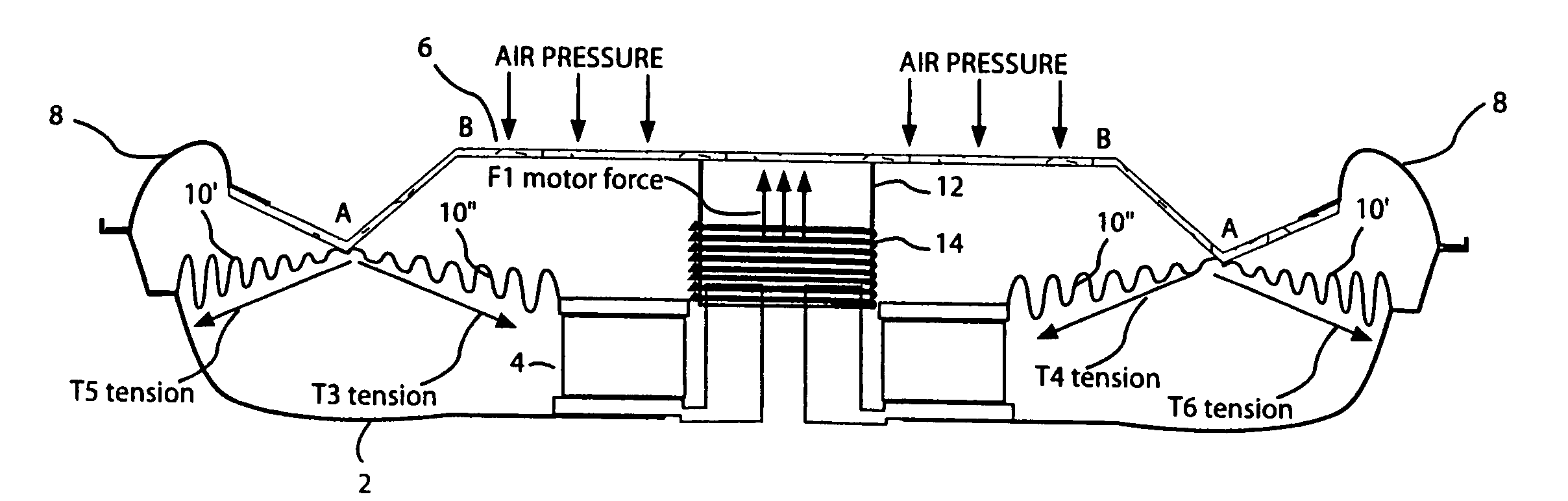
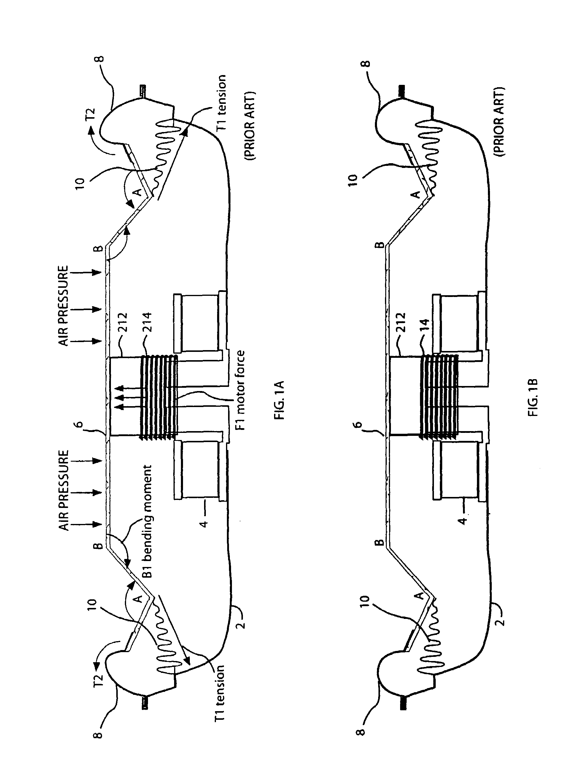
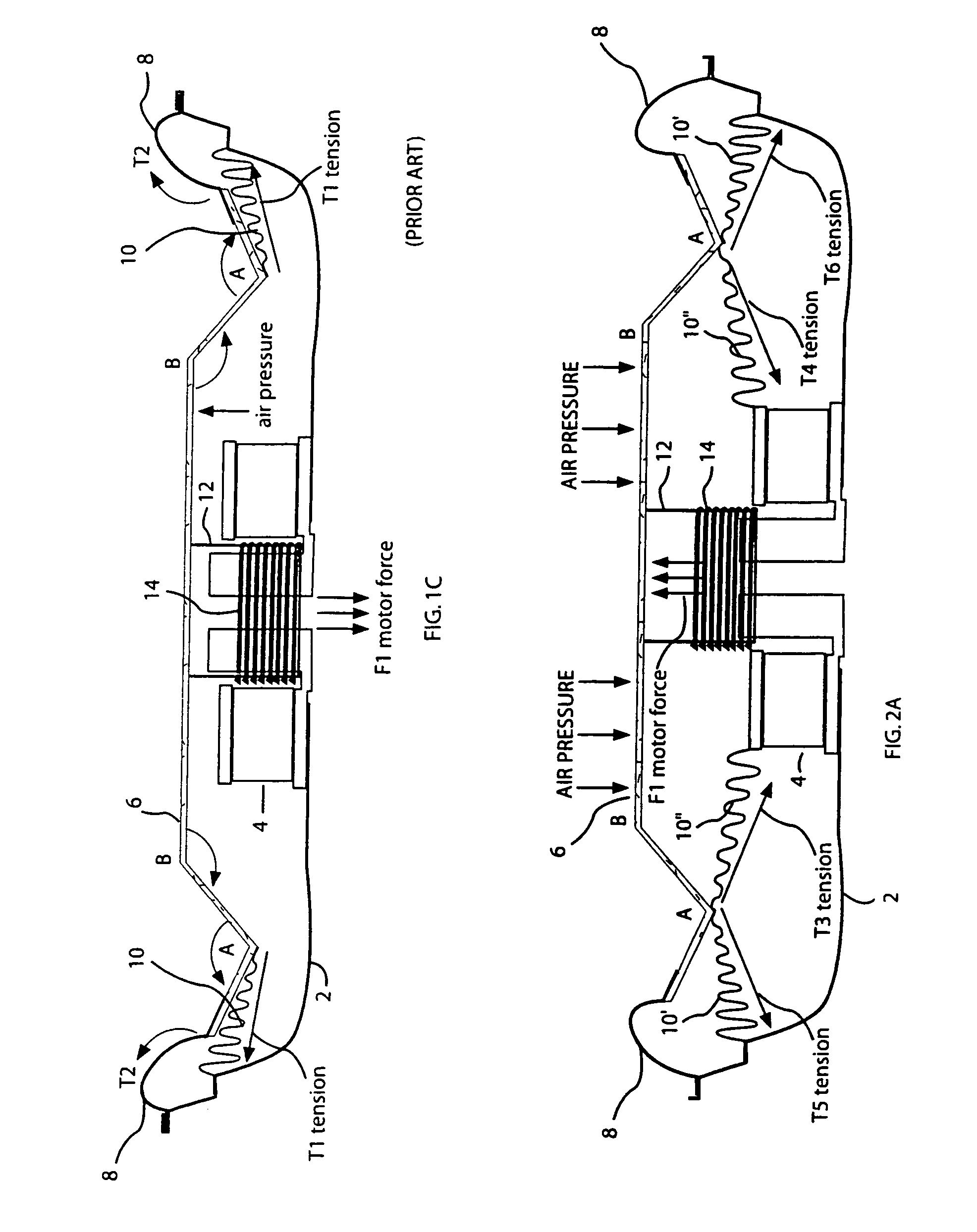
[0043]The present invention provides an speaker design wherein the forces on the cone are balanced at all times throughout the travel of the cone. For the present invention, the basic structure of the speaker of FIGS. 1a–1c is modified. FIG. 2a shows cone 6 in the maximum outward position and since the basic structure here is the same as FIGS. 1a–1c, the same reference numbers are used. The differences in FIGS. 2a–2c with respect to FIGS. 1a–1c is the inclusion of an outer spider 10′ that is similar to spider 10 in FIGS. 1a–1c, and an inner spider 10″ between point A and the top of magnet 4. It can be seen that both spider 10′ and 10″ apply a tensile force to point A of cone 6 on both sides of the center slice of the speaker which is the same for any center slice taken trough the speaker.

[0044]In this configuration, on the left side outer spider 10′ applies force T5 on point A and inner spider 10″ applies force T3 on point A. Similarly on the right side of the speaker, outer spider ...

third embodiment

[0049]FIGS. 4a–c illustrate the three positions discussed above of a speaker with a concave cone of the present invention. This speaker includes a deep basket 20 with a magnet assembly 22 in the center bottom portion of the basket, a concave cone 24 affixed at the center to voice coil tube 32, with voice coil 34 on the lower end thereof. Tube 32 surrounds the central portion of magnet assembly 22. Cone 24 is shown here having a center conical section 26 with the outer rim affixed to downwardly extending ring 38 and an outer conical section 28 flaring out from the top of ring 38 (it should be noted that cone 24 could have a simple conical shape with ring 38 attached to the bottom of cone 24). The outer rim of cone section 28 is attached to the mouth of basket 20 via surround 30. Within the lower portion of basket 20 there is shown an attachment point 40 that encircles and extends a short distance into the inside of the basket. From FIG. 4b where the speaker is unenergized and cone 24...

second embodiment

[0060]FIG. 8c, shows in close-up, the present invention that utilizes surround 110 as described in relation to FIGS. 8a and 8b together with a conventional cone 100 having a blunt outer edge 115. As with the previous embodiment the diameter of the “V” shaped groove on the underside of surround 110 is substantially the same diameter as the outer blunt edge of cone 100 to provide positive centering of surround 110 and cone 100. In this embodiment, the top outer portion of cone 100 is glued to the underside of inner flat ring 116 of surround 110, and the blunt outer edge of cone 100 is glued to extension 118 of surround 110. The differences between the two embodiments of the present invention illustrated and discussed here requires slightly more care in the assembly of the surround and cone of the embodiment of FIG. 8c that in the embodiment of FIG. 8b since that of FIG. 8b provides more of a matched interface between the surround and the cone. Both embodiments result in positive align...


PUM


Abstract

Speaker design / method positively centering speaker components one with the other with a unique design of the surround and radiator. Surround has a main body extending radially through more than 180°, extending from the body there is a flat outer ring and a flat inner ring at substantially 180° radially around the body from the outer ring with a portion of the main body extending below the inner ring, forming a channel between the inner ring and the body portion that extends below it. The radiator has outer and inner edges with a central opening defined by the inner edge, with the outer edge either blunt or defined by a short downward extending ring. The shape and dimensions of the outer edge of the radiator and the channel are substantially the same outer with the radiator edge fitting snugly within the surround channel.

Description

CROSS REFERENCE[0001]This application claims priority co-pending application having Ser. No. 10 / 646,548 filed Aug. 21, 2003, which is an application claiming priority from U.S. provisional application having Ser. No. 60 / 405,416 filed Aug. 21, 2002.BACKGROUND OF THE INVENTION[0002]1. Field of the Invention[0003]This invention relates to passive radiators and audio loud speakers, in particular to the construction of same with minimization of flexure of the radiator and wobble minimization of the voice coil throughout the full range of inner and outer travel of the radiator during operation.[0004]2. Description of the Related Art[0005]In an audio speaker, or transducer, the closer together the points on the speaker frame, or basket, to which the suspension and spider are connected the greater the possibility of rocking, or wobble of the voice coil tube, or bobbin, with respect to the magnet during operation of the speaker. In a conventional speaker, the suspension is attached between t...

Claims


Application Information

Patent Timeline
Patent Type & Authority Patents(United States)
IPC IPC(8): H04R25/00H04R1/00H04R1/10H04R7/12H04R7/20H04R9/06
CPCH04R7/12H04R9/06H04R7/20
Inventor SAHYOUN, JOSEPH Y.
Owner EARTHQUAKE SOUND
Why Eureka
Try Eureka