Heat reclaim refrigeration system and method

a refrigeration system and heat recovery technology, applied in the field of heat recovery refrigeration systems and methods, can solve the problems of low condensing pressure, waste of energy, and insufficient pressure of refrigerant liquid to properly, so as to improve the reclaim of latent heat, save energy, and use less energy.

Inactive Publication Date: 2007-04-03
LESAGE GAETAN +1
View PDF32 Cites 5 Cited by
  • Summary
  • Abstract
  • Description
  • Claims
  • Application Information

AI Technical Summary

Benefits of technology

[0008]The present invention provides a heat reclaim refrigeration system that, advantageously, permits improved reclaim of latent heat generated during the refrigeration cycle, thereby conserving energy and allowing the heat to be used for, among other things, comfort heating of a building. Advantageously, the system allows for variable pressure levels in the compressors, thus permitting compressors to use less energy when less condensing pressure is required for condensing refrigerant vapor in a refrigerant condensing means, such as when the condenser is situated in a colder environment. Further, the system also provides for efficient defrost of evaporators.

Problems solved by technology

Thus, it is entirely conceivable that, in such colder periods or environments, some compressors in a refrigeration system may be unused or operate at lower energy requirements, thus conserving energy.
However, low condensing pressure has negative impacts on some aspects of a typical refrigeration system.
For example, low condensing pressure may result in refrigerant liquid having insufficient pressure to properly feed the refrigerant expansion valves.
This heat is rejected latent heat from the refrigerant, generated by the system, which, unless reclaimed, becomes lost latent heat which, in turn, constitutes wasted energy, especially when the refrigerant condensing means is located outside, such as is typically the case for air-cooled refrigerant condenser means.
This lost latent heat is particularly disadvantageous during colder periods or in colder environments, i.e. where lower condensing pressure may be used to reduce energy requirements for compressors, as it is desirable in such environments to conserve the latent heat for purposes of, among other things, comfort heating of a building in which the refrigeration system is located.
However, low condensing pressure can result in low condensing temperature of refrigerant vapor.
In such circumstances, latent heat released upon heat reclaim will be at the low condensing temperature, which may be insufficient for use of the heat for any useful purpose.
In addition, low condensation pressure generated in compressors may also have negative impacts on system defrost capabilities.
However, low condensing pressure may result in the refrigerant being insufficiently pressurized to circulate thereafter to either the condenser means or the evaporators for subsequent usage thereby.

Method used


Image

  • Heat reclaim refrigeration system and method
  • Heat reclaim refrigeration system and method
  • Heat reclaim refrigeration system and method

Examples


Embodiment Construction

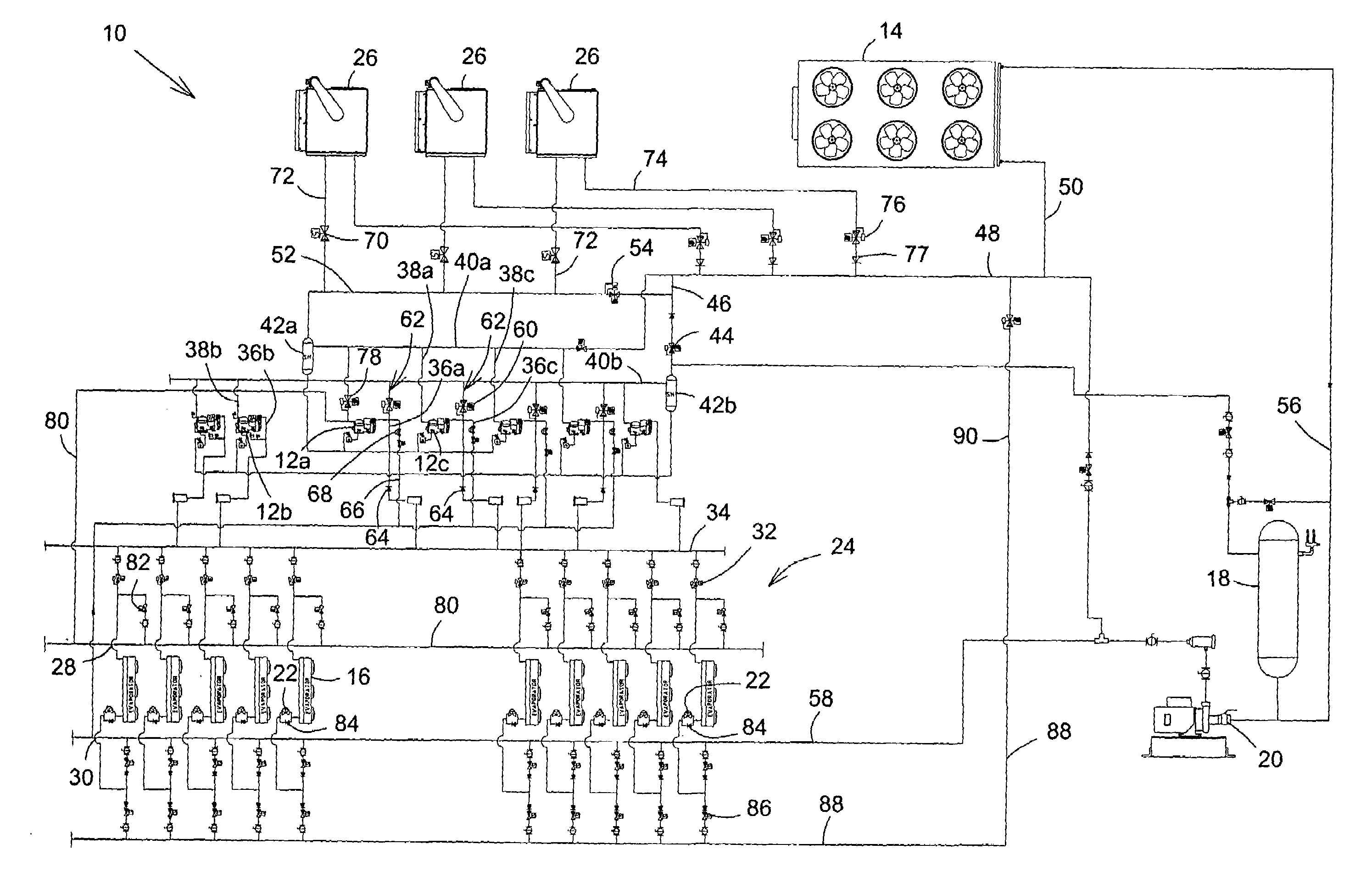
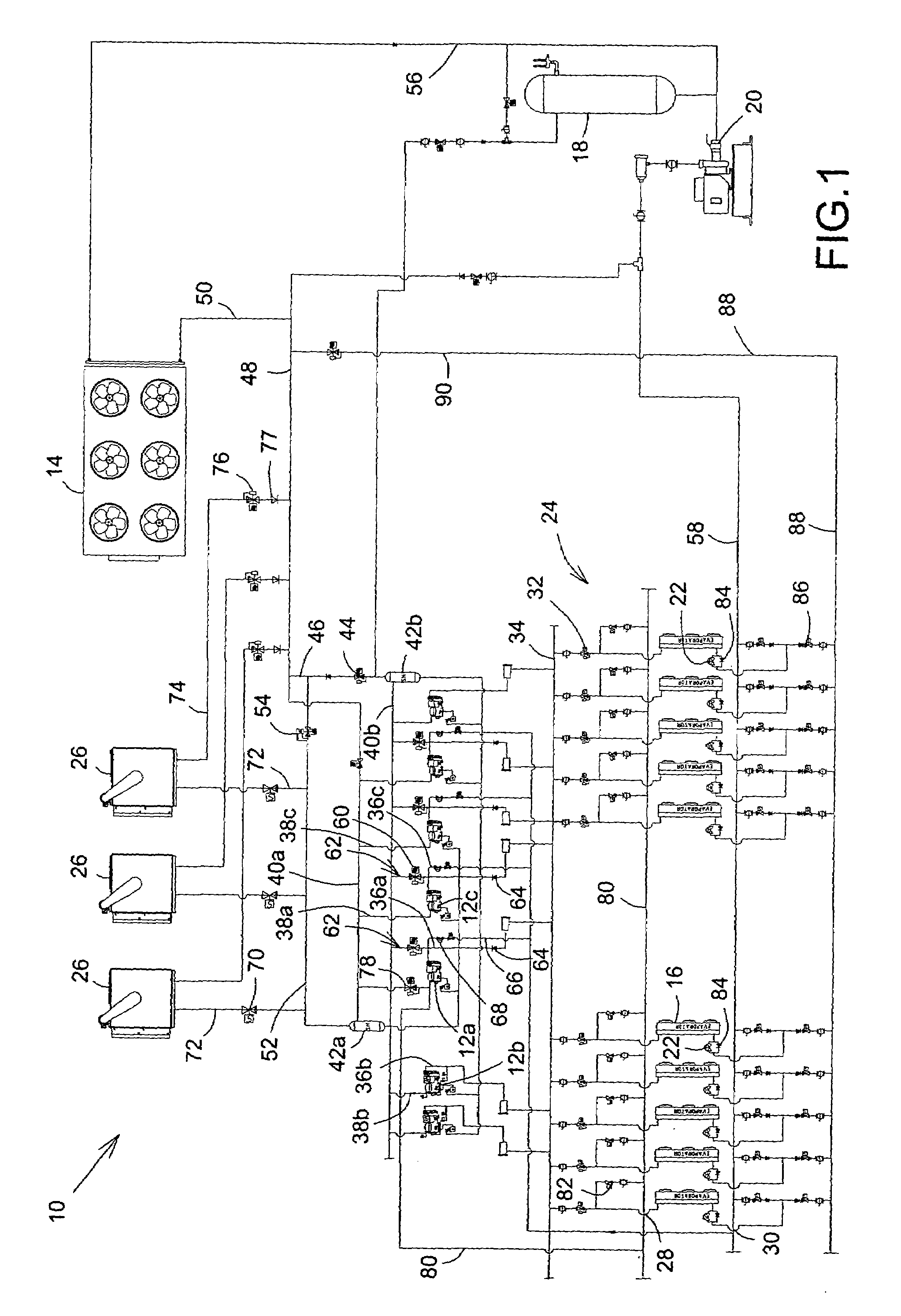
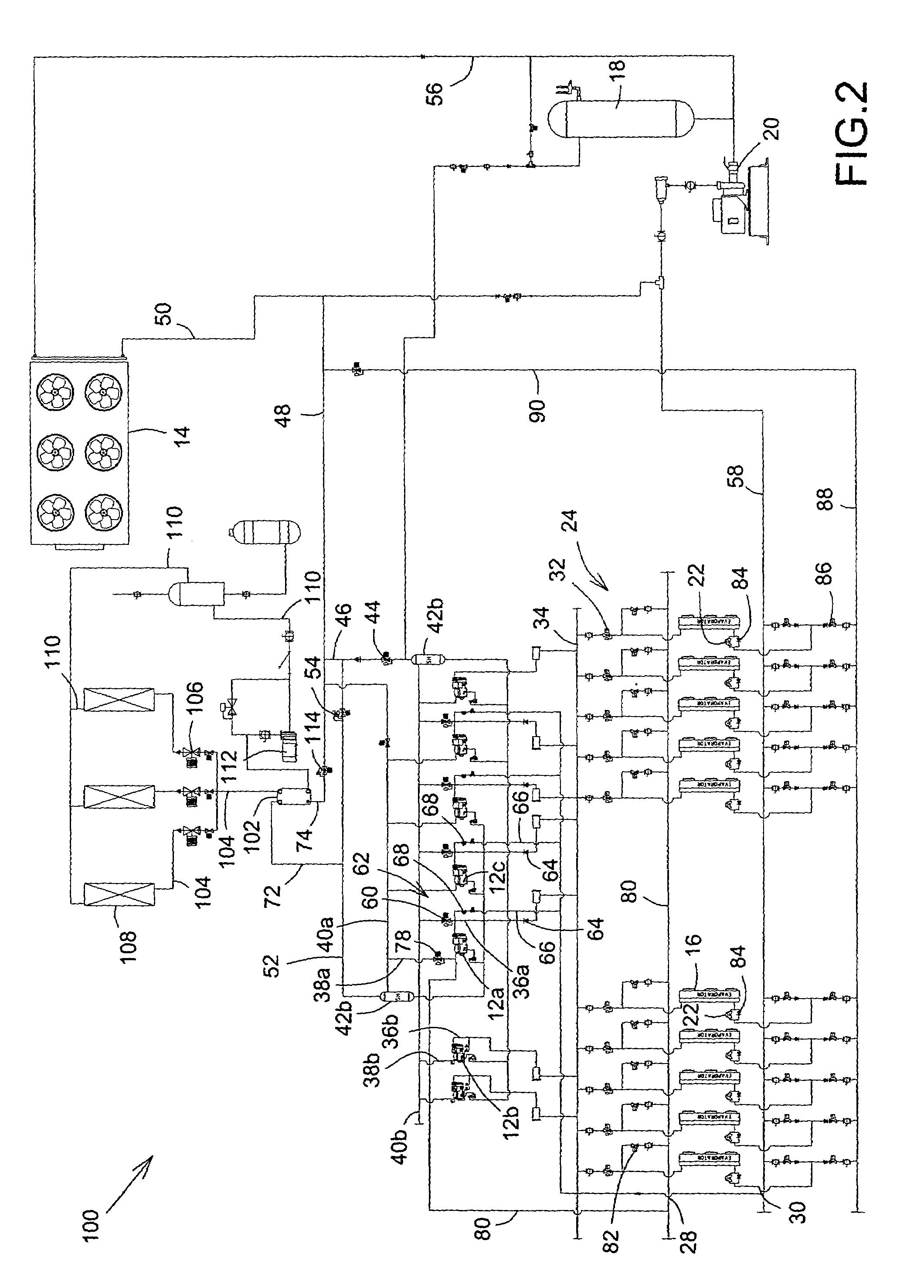
[0021]Reference is now made FIG. 1, a schematic diagram of a heat reclaim refrigeration system, shown generally as 10, having an outdoor air-cooled condenser as refrigerant condensing means and air-to-refrigerant heat reclaim coils as a heat reclaim means, in accordance with a first embodiment of the present invention. Broadly speaking, the system 10 includes two or more compressors 12, an outdoor air-cooled condenser 14 as a refrigerant condensing means, evaporators 16, a refrigerant liquid receiver 18, a refrigerant liquid pump 20, one or more refrigerant expansion valves 22, and a network, shown generally as 24. The network 24 includes a variety of conduits, also referred to as passageways or lines, valves and manifolds, through which the refrigerant liquid pump 20, the evaporators 16, the compressors 12, and the air-cooled condenser 14 are interconnected to circulate the refrigerant. In the embodiment, heat reclaim means, namely refrigerant-to-air heat reclaim coils 26, are also...


PUM


Abstract

A heat reclaim refrigeration system uses a first compressor to elevate the amount of latent heat reclaimable by the system and to reclaim this heat using heat reclaim means, such as heat reclaim coils, for practical applications, such as heating a building. In addition, the system reduces pressure required from a second compressor used for refrigeration, and energy consumed thereby, especially during cold periods of the year when a refrigerant condensing means has lower condensing requirements.

Description

FIELD OF THE INVENTION[0001]The present invention concerns refrigeration systems and methods, more particularly heat reclaim refrigeration systems and methods.BACKGROUND OF THE INVENTION[0002]Refrigeration systems are commonly used in supermarkets to refrigerate or to maintain in frozen state perishable products, such as foodstuff.[0003]Conventionally, refrigeration systems include a network of refrigeration compressors and evaporators. Refrigeration compressors mechanically compress refrigerant vapor, which is circulated from the evaporators, to increase its temperature and pressure. The resulting high-temperature refrigerant vapor, under high-pressure, is circulated to a refrigerant condensing means where the latent heat from the vapors is absorbed. As a result, the refrigerant vapor liquefies into refrigerant liquid. The refrigerant liquid is circulated through refrigerant expansion valves, thereby reducing the temperature and pressure, to the evaporators wherein the refrigerant ...

Claims


Application Information

Patent Timeline
Patent Type & Authority Patents(United States)
IPC IPC(8): F25B5/00
CPCF25B29/003F25B47/022F25B49/027F25B2400/075F25B2400/22
Inventor LESAGE, GAETANKANTCHEV, JORDAN
Owner LESAGE GAETAN
Why Eureka
Try Eureka