Fail safe cooling system for turbine vanes

a cooling system and turbine vanes technology, applied in the field of turbine engines, can solve the problems of insufficient robustness of the cooling system and large structural damage, and achieve the effect of reducing the risk of failur

Inactive Publication Date: 2007-04-03
SIEMENS ENERGY INC
View PDF48 Cites 35 Cited by
  • Summary
  • Abstract
  • Description
  • Claims
  • Application Information

AI Technical Summary

Problems solved by technology

The prior art is replete with examples of cooling systems for turbine vanes; however, these cooling systems are not sufficiently robust in the event of damage to the outer surface of the vane, such as from impact with an object.
Damage to the vane exterior can cause such cooling systems to fail, which, in turn, can quickly cascade into substantial structural damage.

Method used


Image

  • Fail safe cooling system for turbine vanes
  • Fail safe cooling system for turbine vanes
  • Fail safe cooling system for turbine vanes

Examples


Embodiment Construction

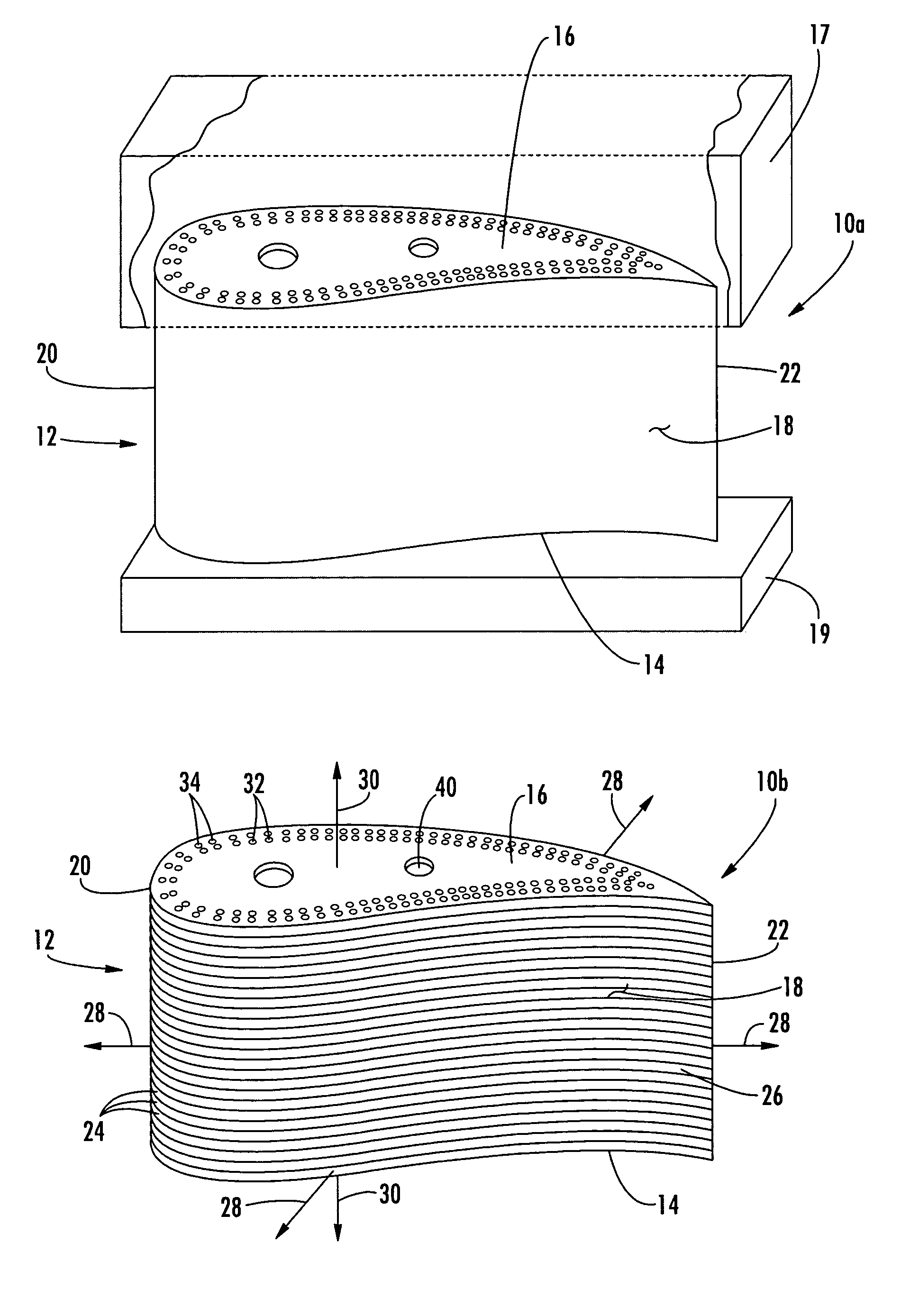
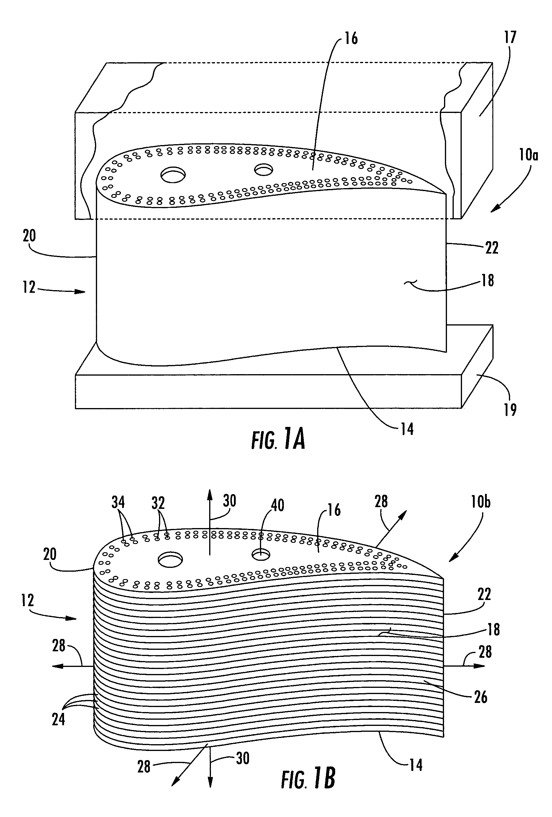
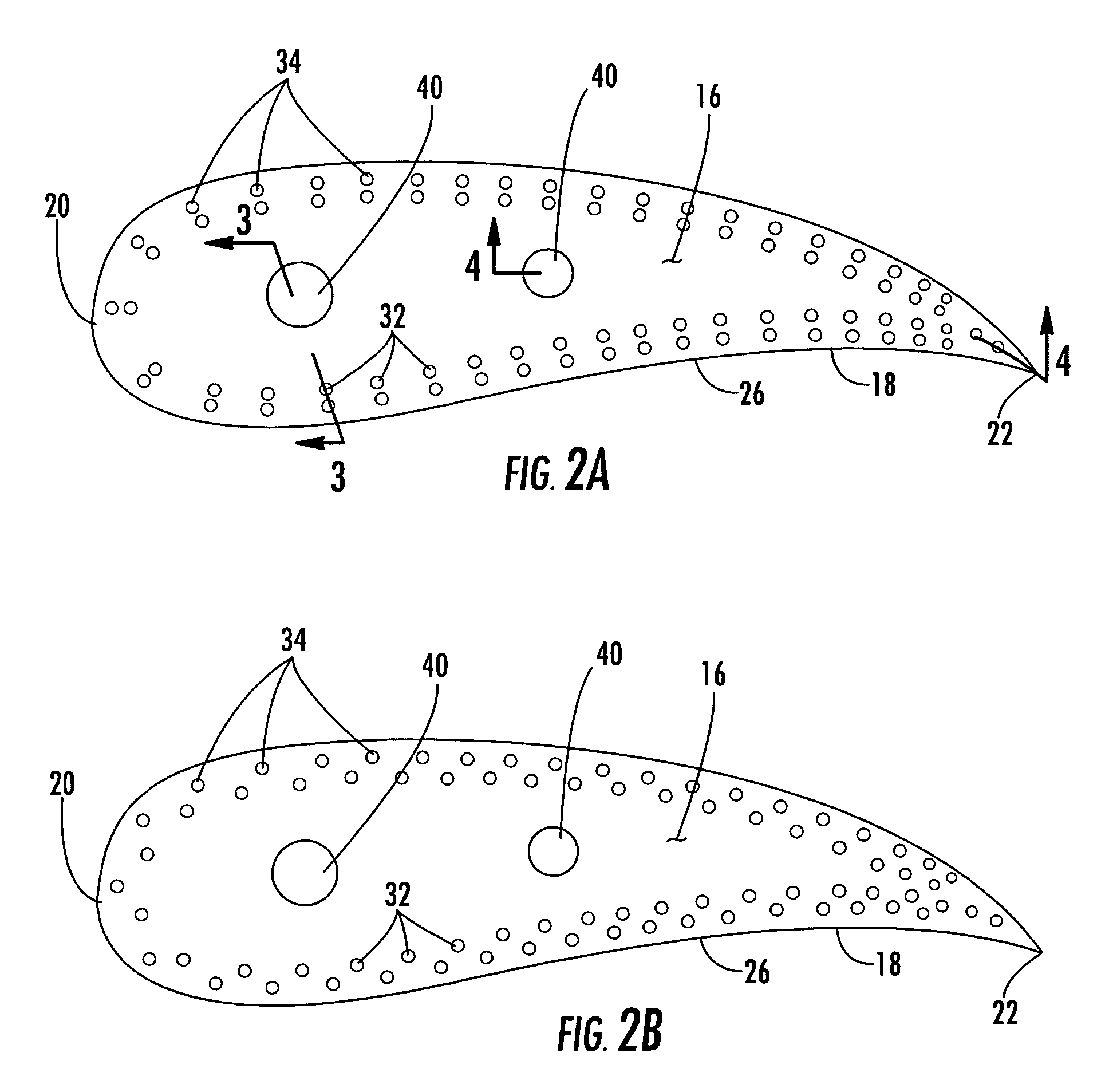
[0024]Embodiments of the present invention address the drawbacks of prior vane cooling systems by providing a robustness to vane surface damage. Embodiments of the invention will be explained in the context of one possible turbine vane, but the detailed description is intended only as exemplary. Embodiments of the invention are shown in FIGS. 1A–4, but the present invention is not limited to the illustrated structure or application.

[0025]The cooling system according to embodiments of the invention is applicable to a variety of turbine vane designs including a single body construction 10a (FIG. 1A) and a stacked wafer construction 10b (FIG. 1B). In either construction, the vane 12 can have a radial inner end 14, a radial outer end 16, and an outer peripheral surface 18. The term “radial” as used herein is intended to describe the direction of the vane 12 in its operational position relative to the turbine. A turbine vane 12 can be bounded at its radial outer end 16 by an outer shroud...


PUM


Abstract

Embodiments of the invention relate to a turbine vane having a fail safe cooling system. According to embodiments of the invention, the vane can have multiple concentric layers of radial cooling holes extending about the vane; each layer being fluidly connected to the adjacent layer or layers. Such fluid communication can occur through one or more plenums in the vane or in the shrouds bounding the radial ends of the vane. Coolant can initially be supplied to the innermost layer of cooling holes. From there, the coolant can sequentially progress through successive outer layers. Between two adjacent layers, the coolant can flow in opposite directions. Not only does such a system provide needed cooling to the vane, but the multilayer redundant cooling system can avoid or delay catastrophic failures that can occur if the vane surface is damaged, such as by impact.

Description

FIELD OF THE INVENTION[0001]The invention relates in general to turbine engine and, more specifically, to a cooling system for stationary airfoils in a turbine engine.BACKGROUND OF THE INVENTION[0002]During the operation of a turbine engine, turbine vanes, among other components, are subjected to the high temperatures of combustion. In order to withstand such an environment, the vanes must be cooled. The prior art is replete with examples of cooling systems for turbine vanes; however, these cooling systems are not sufficiently robust in the event of damage to the outer surface of the vane, such as from impact with an object. Damage to the vane exterior can cause such cooling systems to fail, which, in turn, can quickly cascade into substantial structural damage. Thus, there is a need for a robust cooling system that can avoid or at least delay catastrophic failures that can follow vane surface damage.SUMMARY OF THE INVENTION[0003]Aspects of the invention relate to a fail safe coolin...

Claims


Application Information

Patent Timeline
Patent Type & Authority Patents(United States)
IPC IPC(8): F01D5/18
CPCF01D5/147
Inventor THOMPSON, DANIEL G.
Owner SIEMENS ENERGY INC
Why Eureka
Try Eureka