
Composite Articles Comprising In-Situ-Polymerisable Thermoplastic Material and Processes for their Construction

a thermoplastic material and composite article technology, applied in the field of composite articles, can solve the problems of difficult control of laminate quality, inability to integrate the article, and inability to meet the intended end-use so as to increase the damage tolerance of the composite article, increase environmental resistance, and increase the effect of fibre volume fraction

Inactive Publication Date: 2010-03-11
UNIVERSITY OF LIMERICK +2
View PDF3 Cites 108 Cited by
  • Summary
  • Abstract
  • Description
  • Claims
  • Application Information

AI Technical Summary

Benefits of technology

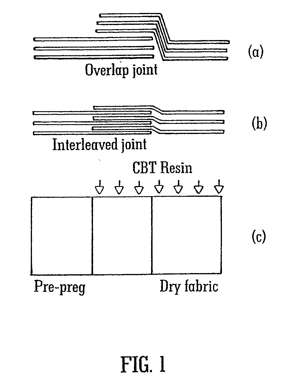
[0040]The process according to the invention may be considered as an integrated process wherein distinct melt fronts are formed. In one embodiment two melt fronts are formed. One melt front may be formed by the thermoplastic material dispersed on the fibrous material. A second melt front may be formed by the additional thermoplastic pre-polymer material that is drawn into the fibrous material. Suitably the additional thermoplastic pre-polymer material is drawn into the fibrous material by vacuum. Each melt front simultaneously infiltrates the fibrous material and meets at an interface to form a fully infiltrated and polymerised composite structure. The use of liquid thermoplastics enables composites having high fibre volume fractions but with desirable composite properties to be reliably achieved.
[0097]Advantages in the end-product include: recyclability of the manufactured (or any waste from the process); increased damage tolerance of the composite article; increased environmental resistance of the composite article (to weathering etc.); the possibility to weld in sections and with better structural integrity (particularly as compared to adhered thermoset sections); reformable and repairable composite articles.

Problems solved by technology

For example, above a certain size, sections of the article are generally constructed separately for later joining together and the integrity of the article is usually compromised along each join between the sections.
Compromising that strength makes the composite less suitable for its intended end-use.
The main disadvantage of the hand layup process is that it is dirty and difficult to control laminate quality.
There are significant health and safety issues associated with the use of uncured resins in the workplace (see below).
However, there are difficulties associated with the manufacture of wind turbine blades from pre-impregnated tape which are largely due to the inflexibility of the process, the long cure cycles associated with the cure of the resin, the necessity to heat the tool, and the health and safety issues associated with manual handling of the tape and partially-cured epoxies (see below).
Furthermore, it is more cost effective for the manufacturer to directly add the resin to the reinforcement rather than pay for the extra step of impregnating the fibres in advance, and the added cost of storing the pre-impregnated materials in freezers.
The general problems encountered by manufacturers of large structures using liquid resin infusion are those of quality.
It can be quite difficult to ensure that the pre-mixed, pre-catalysed resin, usually polyester or vinylester, satisfactorily flows through the entire fibre reinforcement without leaving any dry spots or excessive voids.
This is particularly difficult with the larger blades, as the flow paths can be as long as 50 metres, and vary in thickness from the 100-150 mm at the hub end, to long sections in the fairings which are as thin as 1 to 2 mm.
In thick laminates (greater than 50 mm) this heat of reaction can cause the interior temperature of the laminate to rise above the temperature of the tool, and can degrade the interior of the laminate.
The entire assembly is then adhesively bonded in an extra operation, a process which can be complex and time-consuming.
It is not a simple process, however, to liquid infuse a large thermoset composite wind turbine blade in a single-shot.
Difficulties arise with infiltration of the thick-section solid laminate areas of the blade, for example the spar-caps and hub sections.
However, the process described still necessitates the storage, cutting and manual handling of uncured thermoset prepregs.
In general, there are a number of health and safety problems facing producers of large thermoset composite structures.
The curing of thermoset resins such as polyester, vinylester and epoxy invariably leads to emissions of VOCs into the workplace.
This level is extremely hard to reach with a simple process such as hand layup, and inevitably manufacturers using this process are forced to invest in expensive air handling and treatment equipment.
The second health and safety problem is associated with the handling of uncured epoxy prepregs.
It is known that exposure among workers to such materials can cause contact skin dermatitis, and in some countries (e.g. Sweden) these processes have been prohibited.
Producers of large thermoset composite structures such as wind turbine blades also face major problems in disposing of waste materials from the factory.
Furthermore, once a large thermoset composite structure has been cured, there is no available method of re-working the structure in the case of quality problems, therefore a certain percentage of large blades have to be chopped up and either landfilled or incinerated.
The problem is that thermoset composites cannot be re-processed or recycled.
The same issue occurs with wind turbine blades at their end of life, when they must be disposed of, rather than recycled.
However, there is no teaching or suggestion of a process for the manufacture of large composite articles such as large wind turbine blades made from thermoplastic composites.
Such construction is difficult because of the difficulties involved in producing a fully infiltrated and polymerised large composite structure.

Method used


Image

  • Composite Articles Comprising In-Situ-Polymerisable Thermoplastic Material and Processes for their Construction
  • Composite Articles Comprising In-Situ-Polymerisable Thermoplastic Material and Processes for their Construction
  • Composite Articles Comprising In-Situ-Polymerisable Thermoplastic Material and Processes for their Construction

Examples


example

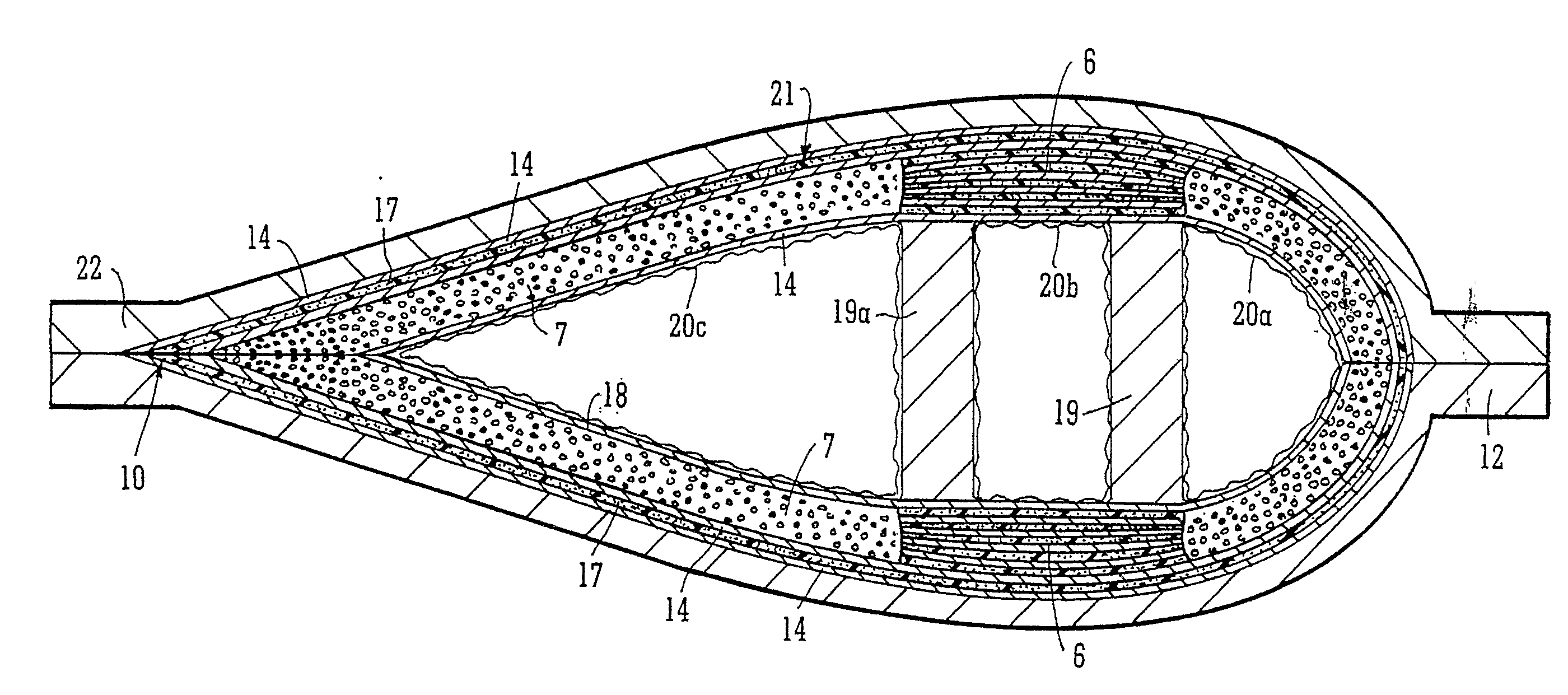
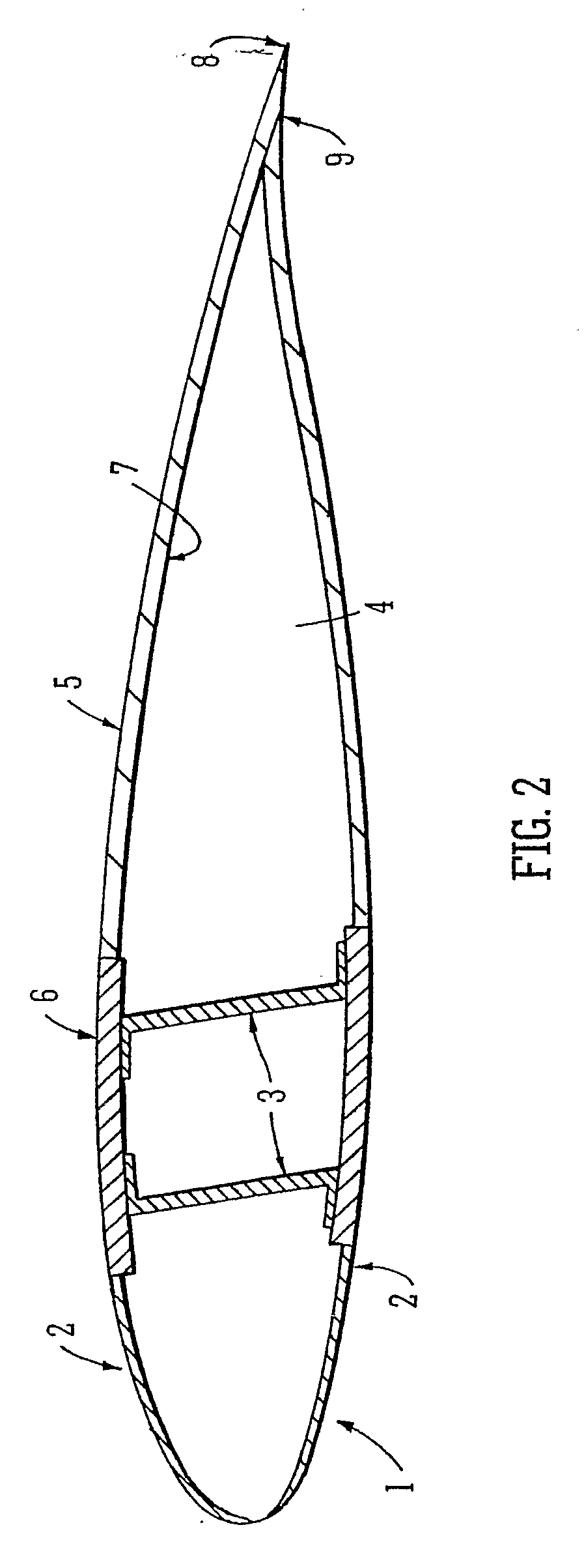
[0139]The following example demonstrates the manufacture of a section of a CBT thermoplastic composite wind turbine blade. It will be appreciated that the process described can also be used to manufacture a whole thermoplastic composite wind turbine blade in a one-shot process. The skilled person will appreciate that blades or blade sections of various sizes could be manufactured using the process according to the invention.

[0140]To demonstrate the process of manufacturing a glass reinforced CBT wind turbine blade, a 4 metre long centre section of a 12.6 m blade was produced. The centre section was manufactured on a high temperature composite tool. This demonstration shows the process that can be used for the entire blade, of any size in length. The following stages were involved in the production of the blade section:[0141]Material Preparation[0142]Tool preparation[0143]Lay-up support[0144]Material lay-up[0145]Heating cycle

[0146]FIG. 2 shows a cross section of a blade section obtai...


PUM

PropertyMeasurementUnit
temperatureaaaaaaaaaa
lengthaaaaaaaaaa
lengthaaaaaaaaaa

Abstract

A process for the manufacture of a composite article is described wherein the process comprises the steps of (i) providing on a tool (22) a fibrous material (14) having associated therewith in at least one region thereof an in-situ polymerisable non-fibrous form of a thermoplastic material; (ii) applying heat and a vacuum to said material; and additionally (iii) drawing into the fibrous material, from a source external to the tool, additional thermoplastic pre-polymer material. The process described is particularly useful for the manufacture of a large composite structure such as thermoplastic composite wind turbine blade, for example.

Description

FIELD OF THE INVENTION[0001]The present invention relates to composite articles such as structural articles or elements and composite materials and processes for their construction. In particular the present invention relates to larger structural elements or articles of manufacture which are generally considered more difficult to manufacture than smaller structural elements.BACKGROUND TO THE INVENTION[0002]In the context of the present invention larger structural elements or objects are of particular interest though the present invention is not limited to those and can be employed for smaller objects. The composite articles, the materials for their production and processes of the invention may be employed in addition to or in full or part substitution for prior art composite articles, materials for their manufacture and processes for their manufacture. The terms structural element, composite article, and the like thus include all articles constructed of composite materials.[0003]In ...

Claims


Application Information

Patent Timeline
Patent Type & Authority Applications(United States)
IPC IPC(8): B32B27/04B05D3/00B05D1/34B32B38/08B64C27/46B29D99/00
CPCB29C70/02B29L2031/085B29C70/345B29K2023/06B29K2033/12B29K2067/00B29K2067/006B29K2069/00B29K2071/00B29K2075/00B29K2077/00B29K2081/04B29K2081/06B29L2031/082B29C70/342Y10T428/249933Y02P70/50B29C70/304
Inventor DOYLE, ADRIANLEE, JAMESARCHER, EDWARDDOYLE, KEITHFEERICK, PATRICKCOLL, SIORAO'BRADAIGH, CONCH RMURTAUGH, ADRIANMALLON, PATRICKSTANLEY, WALTER
Owner UNIVERSITY OF LIMERICK
Learn More