Telescoping wind turbine blade

a technology of wind turbine blades and blades, which is applied in the direction of rotors, vessel construction, other chemical processes, etc., can solve the problems of inability to easily change or remove hub extenders, turbines that do not perform optimally, and lack of teaching to utilize such rotors on wind turbines. achieve the effect of minimizing aerodynamic load and regulating the amount of power intercepted

Inactive Publication Date: 2005-06-07
FRONTIER WIND LLC
View PDF11 Cites 104 Cited by
  • Summary
  • Abstract
  • Description
  • Claims
  • Application Information

AI Technical Summary

Benefits of technology

[0018]The disclosed invention provides a wind turbine blade that is variable in length in order to change the rotor's cross-sectional swept area and to regulate the amount of power intercepted from the wind. In low wind conditions, the blade length is extended to provide a rotor with maximum swept area so that the maximum amount of power can be extracted from the wind. In high wind conditions, the blade is retracted to minimize aerodynamic loading and to keep structural loads within the design criteria.

Problems solved by technology

However, the rotor size selected is always a compromise and there are conditions in which the turbine does not perform optimally because the rotor is too big or too small.
These rotor designs are all for use on aircraft of various sorts and they lack any teaching to utilize such a rotor on a wind turbine.
Hub extenders accomplish the goal of increasing the swept area, but present the following disadvantages:1. Hub extenders cannot be easily changed or removed, because they are relatively heavy devices.
Since it requires a crane and hours of labor to change hub extenders on commercial sized wind turbines, they end up being left in place once they are installed.2. Since hub extenders cannot be easily removed, extra loads are placed on the turbine every time high winds occur, and3. The length of the hub extenders is limited by the strength of the existing drive train and other components.
Since the entire drive train cannot be economically upgraded, the use of hub extenders is limited as a way of increasing the energy output of a wind turbine.
One design shown in U.S. Pat. No. 4,715,782 incorporated herein by reference, reduces the efficiency of the blade by turning 90 degrees and causing drag.
These tip brakes are not designed to operate at any position other than fully rotated, or fully lined up with the blade.
While tip brakes are made up of a fixed and a moveable blade section, they:1. do not allow the effective length of the blade to be changed;2. do not improve the power output of the blade;3. do not optimize the pitch of the end of the blade with changes in length, and4. do not operate at positions intermediate to the fully deployed or fully lined up positions.

Method used


Image

  • Telescoping wind turbine blade
  • Telescoping wind turbine blade
  • Telescoping wind turbine blade

Examples


Embodiment Construction

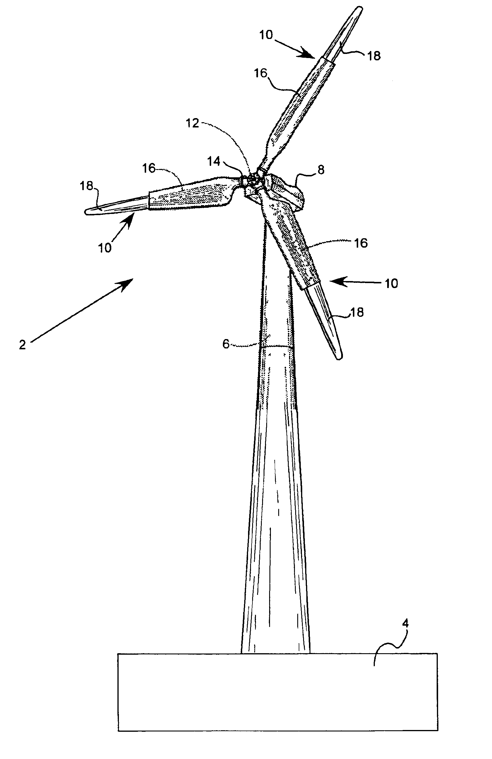
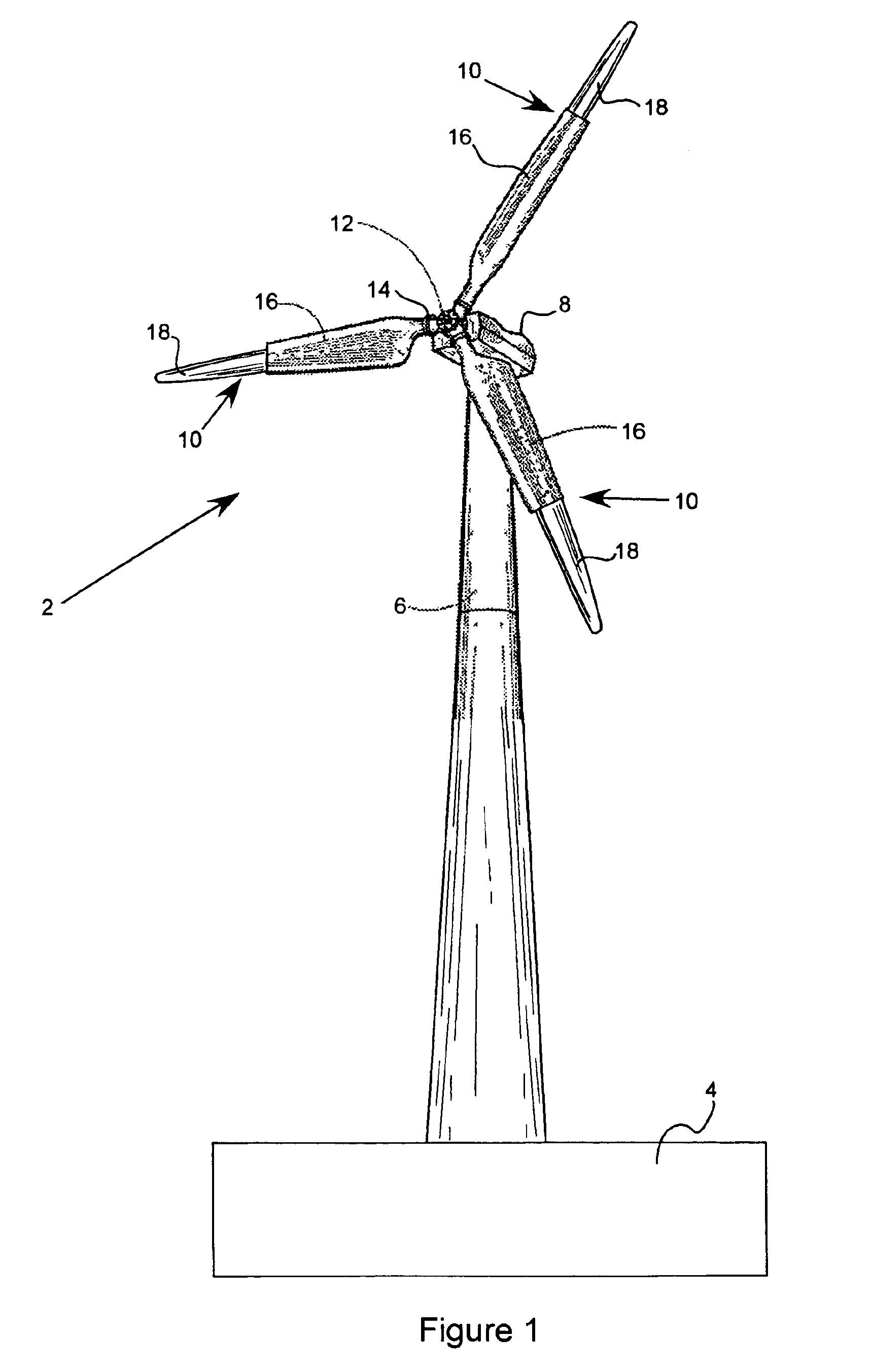
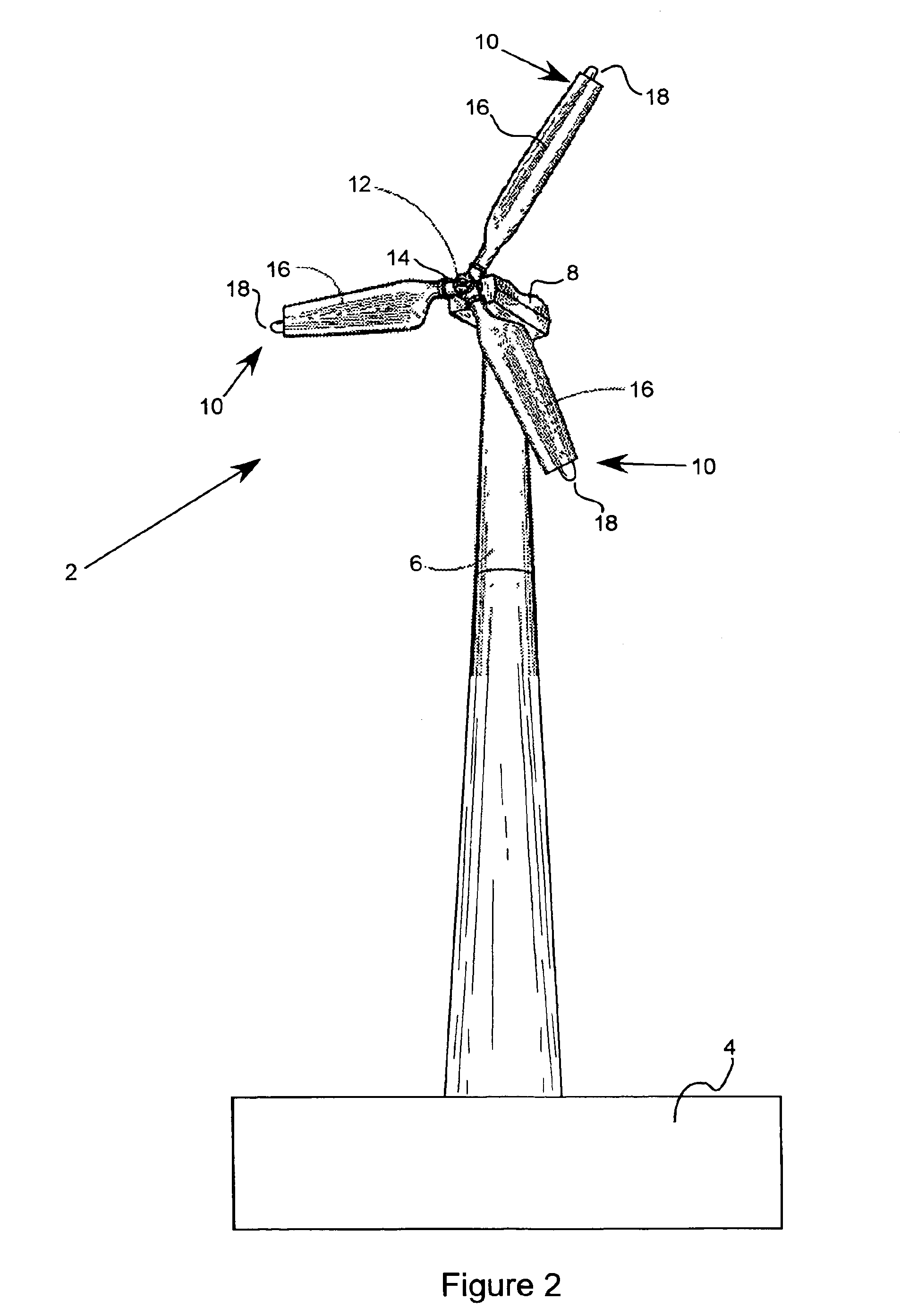
[0051]The variable length rotor blade of the present invention is described herein for use with an electricity-producing wind turbine 2 as shown in FIG. 1. The wind turbine 2 consists of a foundation 4, a tower 6, a nacelle 8, and a number of variable length blades 10 according to the present invention. There are typically two or three blades 10 on an electricity-producing wind turbine 2. The blades 10 are attached to a hub 12 by a bolt flange 14. Alternatively, the blades 10 can incorporate studs that are embedded in the structure of the blade and bolted to the hub 12. The bolt flange 14 on most wind turbines 2 is one of several standard sizes so that retrofitting existing wind turbines 2 with new blades 10 is relatively simple. U.S. Pat. No. 4,915,590, the teachings of which are incorporated herein by reference, describes various types of blade-hub connections.

[0052]The variable length blades 10 consist of two portions. There is a fixed blade section 16 which is rigidly attached t...


PUM


Abstract

A wind turbine blade made of a fixed blade section with an integral mounting flange for attachment to a wind turbine hub. A moveable blade section is attached to the fixed blade section and is free to move in a longitudinal direction relative to the fixed blade section. A positioning device controllably positions the moveable blade section to vary the overall length of the blade. This allows the wind turbine's rotor diameter to be adjusted. The rotor diameter can be increased in order to provide high power output in low wind conditions and it can be decreased in order to minimize loads in high wind conditions.

Description

FIELD OF THE INVENTION[0001]This invention relates to blades for wind turbines. Specifically, the invention relates to a telescoping blade where the length of the blade is variable.BACKGROUND OF THE INVENTION[0002]Wind turbines create power proportional to the swept area of their blades. Increasing the length of a wind turbine's blades increases the swept area, which produces more power. A wind turbine's generator, gears, bearings and support structure must be designed around the expected wind load and power production. At low wind speeds very long blades are desirable to get as much power as possible out of the available wind. At high wind speeds a wind turbine must control the power production and the mechanical loads developed. Eventually, the wind becomes high enough that the turbine must shut down to avoid damaging components, so short blades are desirable to keep the turbine producing power in high winds.[0003]The choice of a rotor diameter for a wind turbine is a design trade...

Claims


Application Information

Patent Timeline
Patent Type & Authority Patents(United States)
IPC IPC(8): F03D7/02F03D7/00
CPCF03D7/0236F05B2240/2021Y10S416/04Y02E10/721Y02E10/723F05B2240/313Y02E10/72
Inventor DAWSON, MARK H.WALLACE, JACK A.
Owner FRONTIER WIND LLC
Why Eureka
Try Eureka