Wind turbine blade

a technology of wind turbine blades and blades, which is applied in the manufacture of final products, machines/engines, wind energy generation, etc., can solve the problems of difficult control of the tolerances of the two half shells, notoriously difficult to manufacture, and associated cost and probability of manufacturing defects, so as to reduce the number of webs and thereby the amount of material used. , the effect of simple structur

Active Publication Date: 2009-03-12
BLADE DYNAMICS LTD
View PDF19 Cites 106 Cited by
  • Summary
  • Abstract
  • Description
  • Claims
  • Application Information

AI Technical Summary

Benefits of technology

[0043]A spar made up of smaller components is beneficial as the spar components can be standardised, cheap to produce, elements which can be connected together to form a more complex shape as typically required for a wind turbine blade spar.
[0044]Preferably one or more of the beams is an

Problems solved by technology

As the size of the blades increase, so does the associated cost and probability of manufacturing defects, as large, high quality, components are notoriously difficult to manufacture.
Furthermore, as the blades get larger, it becomes more difficult to control the tolerances of the two half shells thereby making it difficult to register the edges of the two half shells in order to join them together.
Notwithstanding the above, the la

Method used


Image

  • Wind turbine blade
  • Wind turbine blade
  • Wind turbine blade

Examples


Embodiment Construction

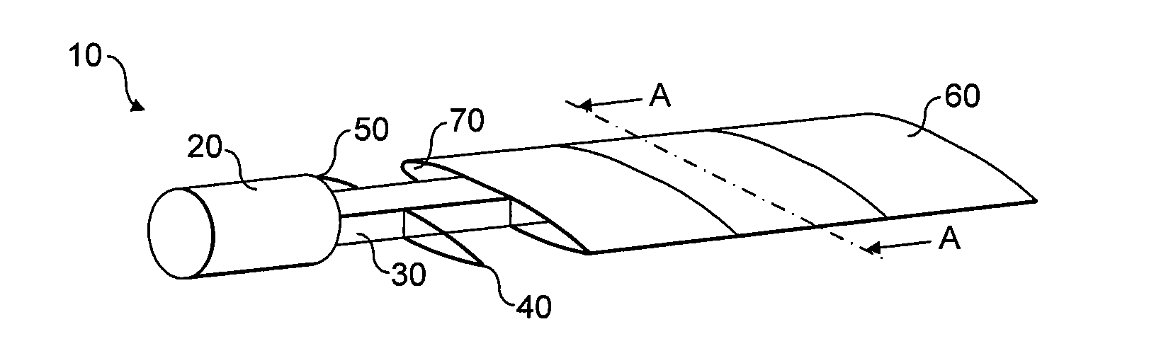
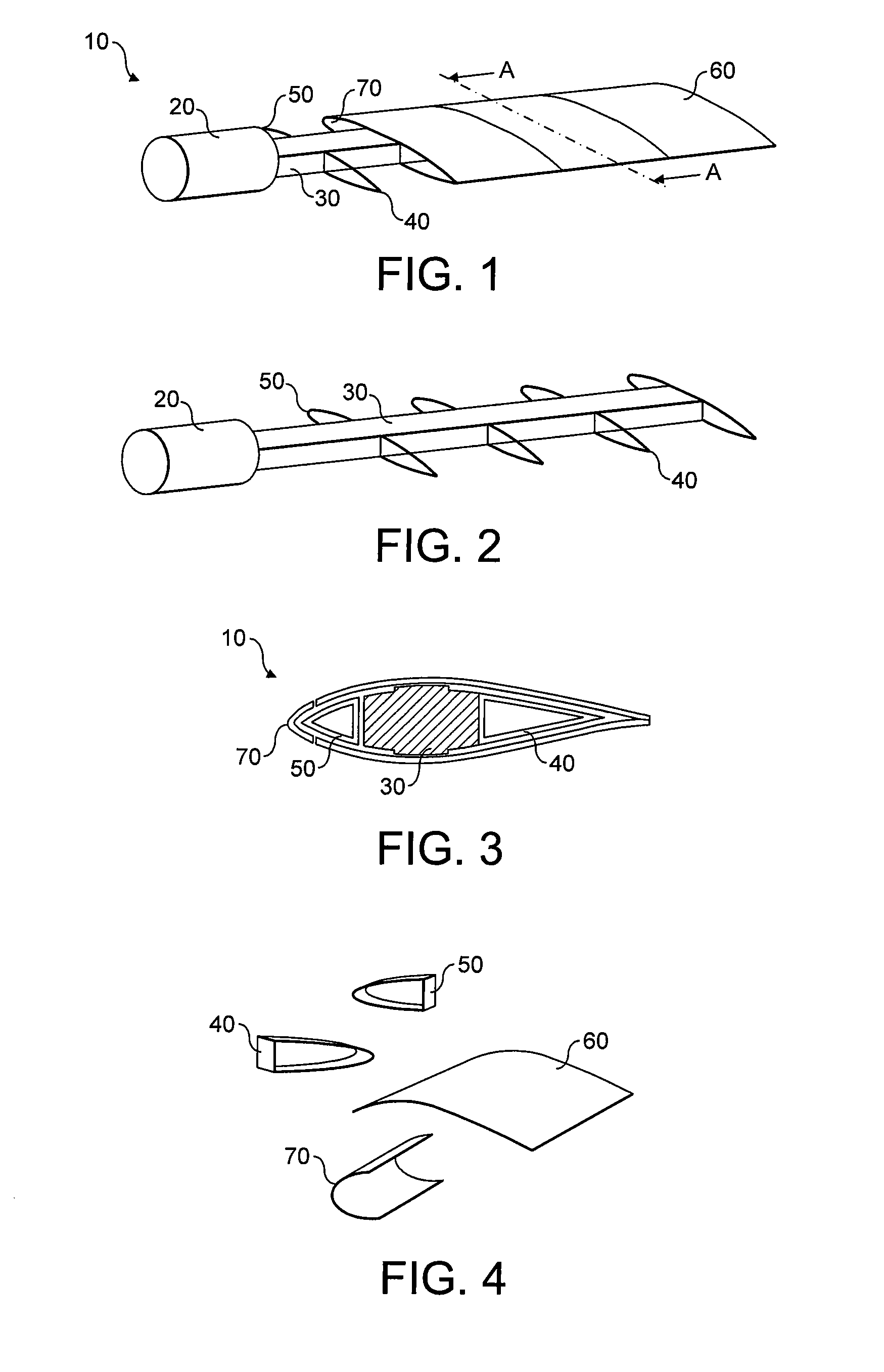
[0080]FIG. 1 shows a partially complete wind turbine blade 10 comprising a load bearing spar 30 which is connected to a root subassembly 20 as will be described in greater detail below. The spar 30 supports frame members 40, 50 onto which skin panels 60, 70 are mounted to form the outer surface of the blade 10.

[0081]In the example shown in FIGS. 1 to 3, the frame members 40, 50 are made of carbon fibre reinforced plastic and consist of leading side frame members 50 and trailing side frame members 40. As shown, the frame members 40, 50 are shaped to largely correspond to the cross-sectional profile of the blade 10.

[0082]The skin panels 60, 70 are attached to the frame members 40, 50 and spar 30 to form a continuous outer skin. The leading edge skin panels 70 are attached to the leading side frame members 50 and the remaining skin panels 60 are attached to the leading side frame members 50, the spar 30 and trailing side frame members 40.

[0083]The skin panels 60 are made of glass fibre...


PUM

PropertyMeasurementUnit
Lengthaaaaaaaaaa
Lengthaaaaaaaaaa
Lengthaaaaaaaaaa

Abstract

Apparatus and methods related to wind turbine blades and manufacturing of the blades.

Description

CROSS-REFERENCE TO RELATED APPLICATIONS[0001]This application claims benefit of Great Britain patent application serial number ______ (not yet known), filed Sep. 11, 2007, which is herein incorporated by reference.BACKGROUND OF THE INVENTION[0002]1. Field of the Invention[0003]The present invention relates to wind turbine blades and methods of manufacture for wind turbine blades.[0004]2. Description of the Related Art[0005]The current approach to manufacturing wind turbine blades is to produce each blade either as two half shells and a spar, or as two half shells with an integral spar. In both cases, the two half shells are bonded together along their edges to form the complete blade.[0006]The blades are typically made from fibre reinforced plastic using either resin infusion or prepreg techniques. In both cases, the blades are produced in large labour and capital intensive facilities and then transported to the location of the wind turbine or wind farm.[0007]The shortcomings of the...

Claims


Application Information

Patent Timeline
IPC IPC(8): F01D5/18F03D1/06F01D5/30B23P15/04
CPCF03D1/0675Y10T29/49826F05B2230/60F05B2250/71F05B2280/4003F05B2280/6003F05B2280/6011F05B2280/6013F05B2280/702F05C2225/00F05C2253/04F05C2253/12F05C2253/16F05C2253/22Y02E10/721Y10T29/49337F05B2230/23F05B2240/302Y02E10/72Y02P70/50
Inventor RUDLING, PAUL
Owner BLADE DYNAMICS LTD
Why Eureka
Try Eureka