Weight plate for interlocking and weight adjustment

a weight plate and interlocking technology, applied in the field of weight plates, can solve the problems of difficult to pick up a weight plate, the flat sided weight plate does not have a convenient hand hold for the user, and the lifting maneuver is more difficult to achieve. , to achieve the effect of improving the comfort of the user

Active Publication Date: 2007-04-03
USA SPORTS
View PDF64 Cites 42 Cited by
  • Summary
  • Abstract
  • Description
  • Claims
  • Application Information

AI Technical Summary

Benefits of technology

[0006]A weight plate having integrally formed handles is provided. The weight plate has a weight plate body having an outer periphery, a first side, and a second side that is substantially flat. The weight plate also has a central bore extending axially through the body, a raised flange member forming a portion of the outer periphery on the first side, and at least one handle opening extending axially through the body and radially through at least a portion of the outer periphery. Each handle opening in cooperation with the raised flange member define a handle sufficient for a human hand to grip. Where multiple handle openings are employed, including two or more handle openings, the handle openings are equiangularly spaced apart. Additionally, each handle opening includes edge surfaces which are rounded to improve the comfort of the user. In one embodiment, the weight plate further includes an interlock for interlocking the weight plate with another weight plate when positioned together. In another embodiment, the weight plate further includes a pock defined in the weight plate. The pock allows the weight of the weight plate to be adjusted to a desired weight by allowing additional material to be added to the pock.

Problems solved by technology

One major problem with free weight lifting and a cause of many accidental injuries is that it is difficult to pick up a weight plate, particularly disc-shaped plates having substantially flat sides.
The problem, simply stated, is that a flat sided weight plate does not have a convenient hand hold to be grasped by the user for lifting it off of a flat surface, such as the floor or a stack of adjacent weight plates.
Of course, the heavier the weight plate, the more difficult this lifting maneuver becomes.
Lifting a weight plate according to the generally accepted method described above can cause injury if the weight plate slips out of the grasp of the user and falls on his or her toes or fingers.
The same problems are encountered, however, when an individual attempts to lift the weight plate by its circumferential flange.
The typical weight plate is not only difficult to lift off a flat surface, as noted above, but is also difficult to hold and raise up, perhaps to chest level, to mount the weight plate on an exercise apparatus.
Likewise, removing a weight plate from a relatively high position on an exercise apparatus is also difficult and, if not done with care, may result in injury to the individual removing the weight plate.
Intricate plate designs typically cost more to manufacture than a standard weight plate, thus creating a unit cost that the market is unwilling to bear.

Method used


Image

  • Weight plate for interlocking and weight adjustment
  • Weight plate for interlocking and weight adjustment
  • Weight plate for interlocking and weight adjustment

Examples


Embodiment Construction

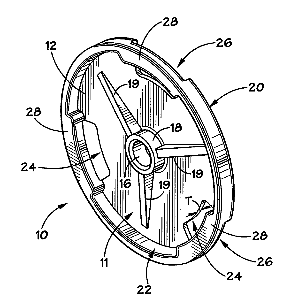
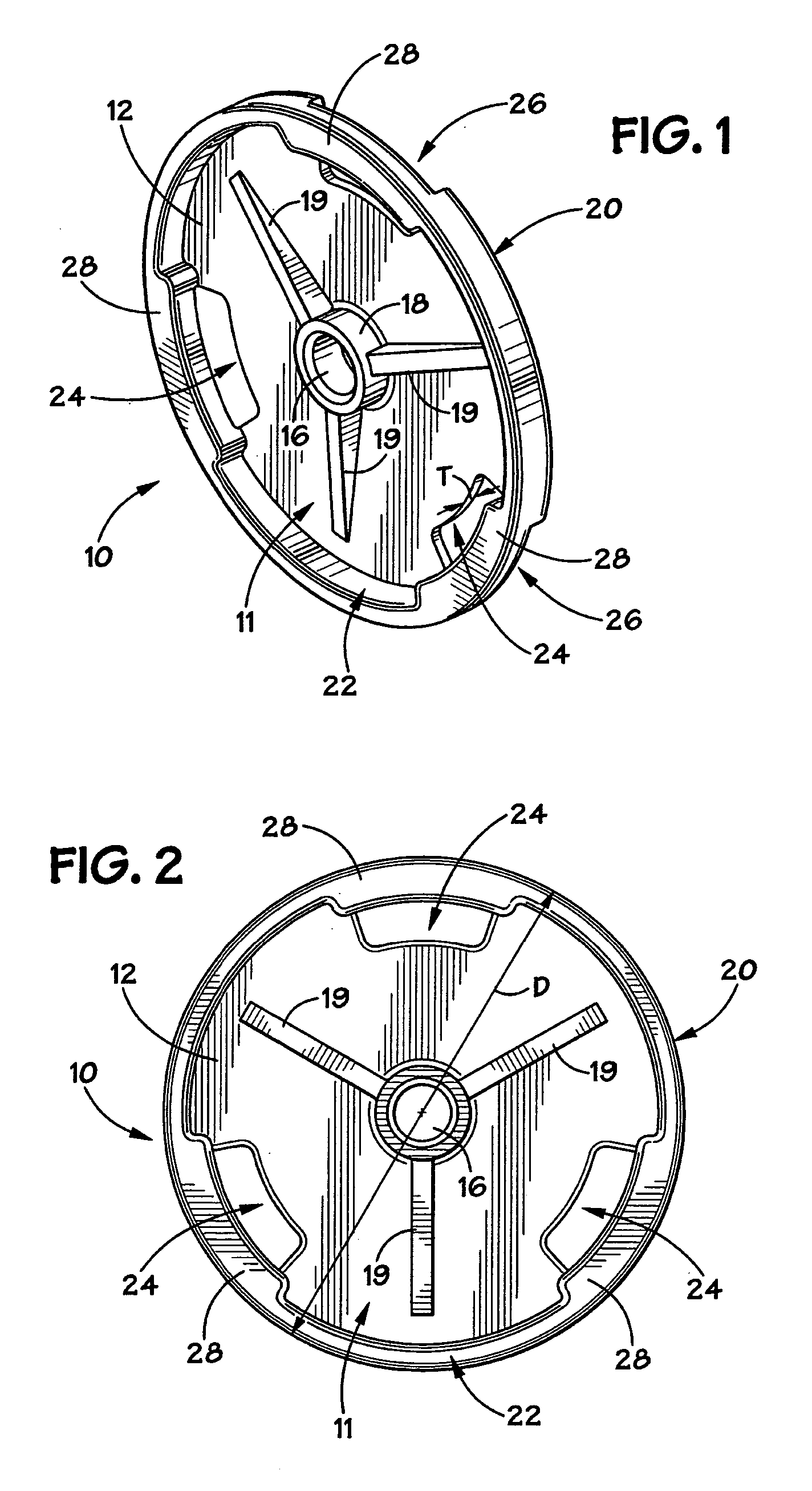
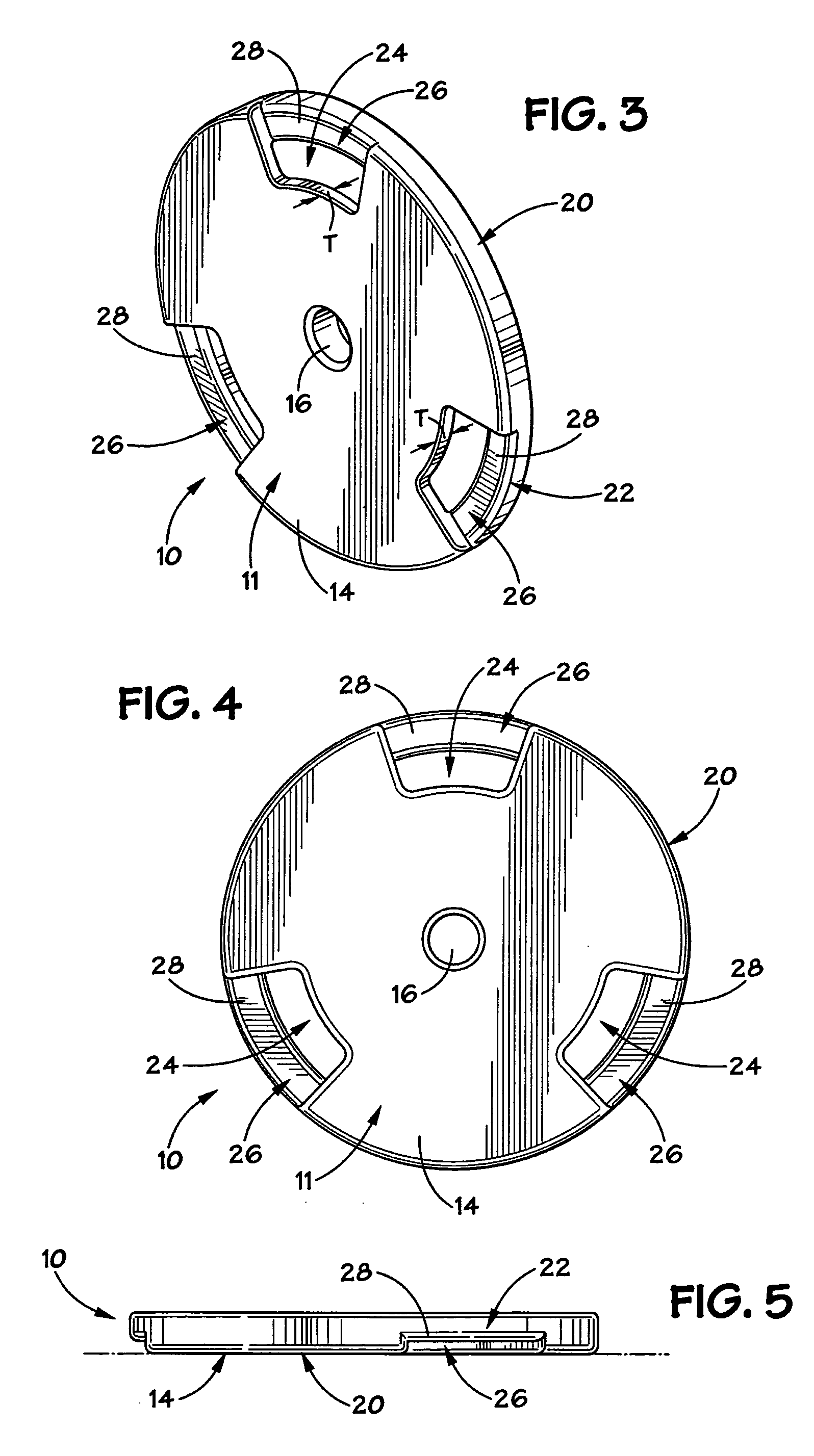
[0016]The present disclosure will now be described more fully with reference to the accompanying drawings in which a preferred embodiment of the disclosure is shown. This disclosure may, however, be embodied in many different forms and should not be construed as being limited to the embodiment set forth herein.

[0017]Referring to FIGS. 1–5, a weight plate 10 in accordance with certain teachings of the present disclosure is shown. Weight plate 10 may be cast, rubber coated, and / or polyurethane coated. Weight plate 10 includes a substantially flat body 11 defined by a first planar surface or side 12 and a second planar surface or side 14. The planar surfaces 12, 14 are generally opposed and define the axial thickness T of weight plate 10. FIGS. 1 and 2 depict the first side of weight plate 10, while FIGS. 3 and 4 depict the second side of weight plate 10. A centrally located bore 16 defines the rotational axis of plate 10 and is adapted to receive a mounting member (not shown), such as...


PUM


Abstract

A weight plate have integrally formed handles is provided. The weight plate has a weight plate body having an outer periphery, a first side, and a second side that is substantially flat. The weight plate also has a central bore extending through the body, a raised flange member forming a portion of the outer periphery on the first side, and at least one handle opening extending through the body and through ht least a portion of the outer periphery. The handle formed by each handle opening, the corresponding recess, and the raised flange member is sufficient for a human hand to grip. In one embodiment, the weight plate further includes an interlock for interlocking the weight plate with another weight plate when positioned together. In another embodiment, the weight plate further includes a pock defined in the weight plate. The pock allows the weight of the weight plate to be adjusted to a desired weight by allowing additional material to be added to the pock.

Description

FIELD OF THE DISCLOSURE[0001]The present disclosure relates generally to physical fitness equipment, and more specifically to an improved weight plate that may be used during weight lifting.BACKGROUND OF THE DISCLOSURE[0002]Free weight exercises generally require weight plates for use with barbells or dumbbells. The weight plates are typically disc-shaped and include a central opening for receiving a barbell or dumbbell bar through the central opening. One major problem with free weight lifting and a cause of many accidental injuries is that it is difficult to pick up a weight plate, particularly disc-shaped plates having substantially flat sides. Most users can typically handle the lighter weights of 5 or 10 pounds without too much difficulty. But as the size and weight of the weight plate increases, one must be very careful to avoid injury. The problem, simply stated, is that a flat sided weight plate does not have a convenient hand hold to be grasped by the user for lifting it of...

Claims


Application Information

Patent Timeline
Patent Type & Authority Patents(United States)
IPC IPC(8): A63B21/072A63B21/06A63B21/075
CPCA63B21/0728Y10S482/908
Inventor LIEN, LOUIS
Owner USA SPORTS
Why Eureka
Try Eureka