Intervertebral implant

a technology of intervertebral implants and implants, which is applied in the field of intervertebral implants, can solve the problems of unfavorable break-in of carrier plates in the dorsal area of the vertebral body

Active Publication Date: 2007-04-03
AESCULAP AG
View PDF253 Cites 169 Cited by
  • Summary
  • Abstract
  • Description
  • Claims
  • Application Information

AI Technical Summary

Benefits of technology

[0009]The convex joint surface extends in the middle area of the carrier plate on both sides of the center line of the carrier plate, which center line extends between the front edge and the rear edge to an approximately equal extent and projects at its end facing the rear edge farther away from the carrier plate than at its end facing the front edge. A joint surface is thus obtained that is arranged centrally in the carrier plate and nevertheless forms a fulcrum that is displaced in the dorsal direction, i.e., toward the rear edge. The forces can be introduced approximately centrally over the entire joint surface, so that the risk for one-sided loading of the carrier plates is markedly reduced.
[0010]It is especially advantageous if at least one of the joint surfaces is arranged in an inlay that is fixed in the carrier plate; in particular, both joint surfaces may be arranged in such inlays.
[0011]It is advantageous if these inlays are inserted into a recess of the carrier plates, so that they are secured against a lateral displacement as a result.
[0015]It is favorable if a depression is arranged in the carrier plate with the convex sliding surface between this joint surface and the front edge of the carrier plate. This depression makes it possible to receive parts projecting in case of extreme pivoting angles at the other carrier plate, so that the pivoting angle can be increased as a result.

Problems solved by technology

This may lead to undesired break-ins of the carrier plates in the dorsal area of the vertebral body, especially in the case of weakened vertebral bodies.

Method used


Image

  • Intervertebral implant
  • Intervertebral implant
  • Intervertebral implant

Examples


Embodiment Construction

[0022]Although the invention is illustrated and described herein with reference to specific embodiments, the invention is not intended to be limited to the details shown. Rather, various modifications may be made in the details within the scope and range of equivalents of the claims and without departing from the invention.

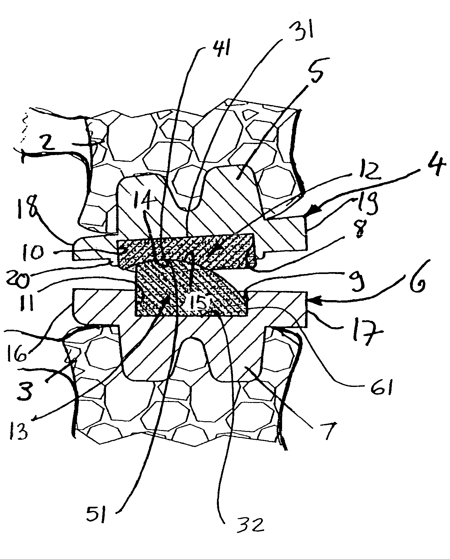
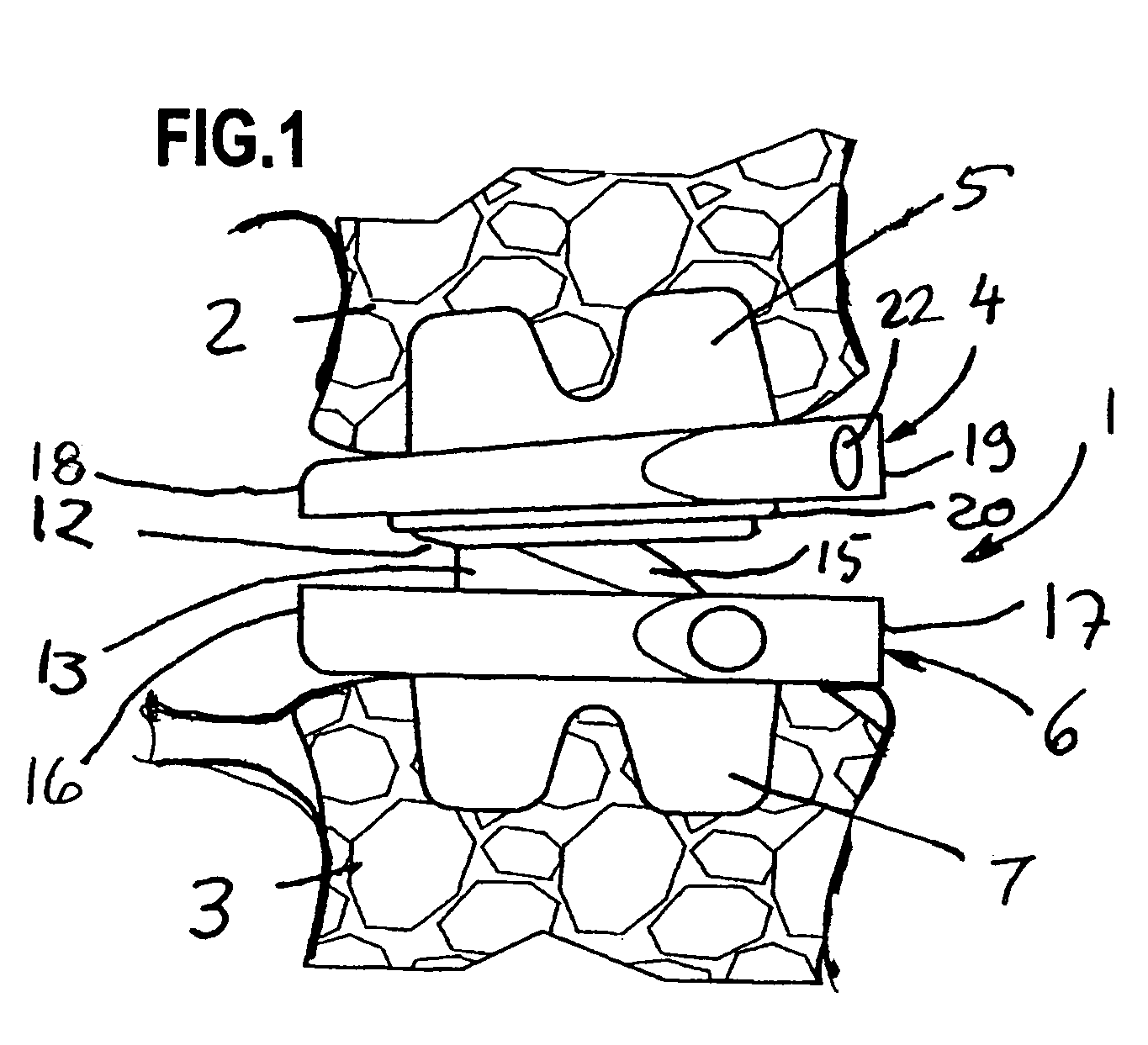
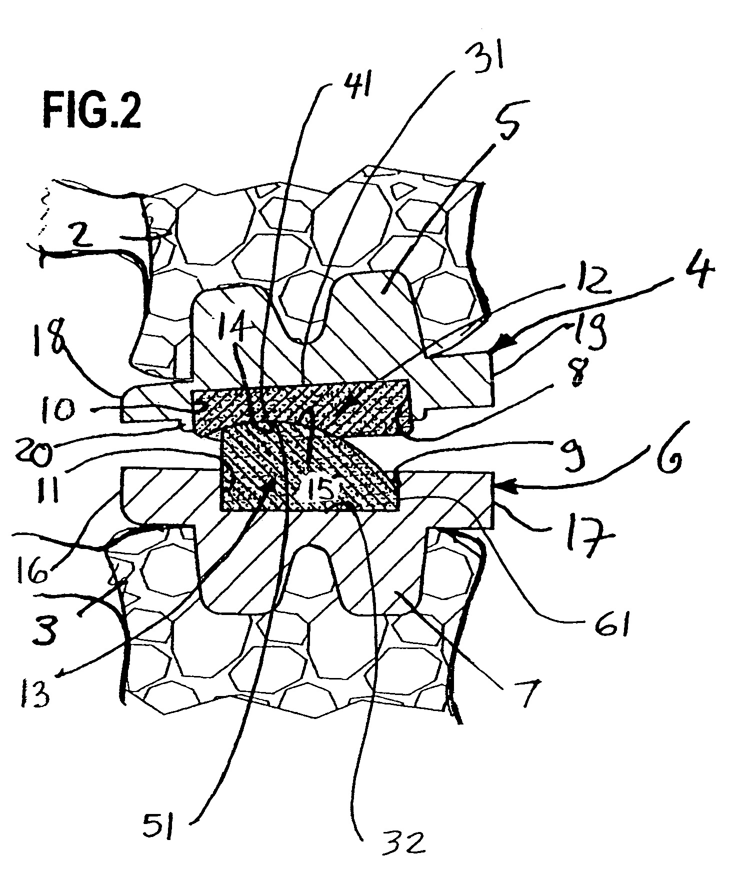
[0023]The intervertebral implant 1 shown in the figures is used as a replacement for a removed intervertebral disk and is inserted between two vertebral bodies 2, 3. It comprises a first carrier plate 4, which carries rib-shaped projections 5 on its rear side for anchoring in a vertebral body as well as a second carrier plate 6, which likewise carries corresponding projections 7 on its rear side for anchoring in the adjacent vertebral body. The inner sides of the carrier plates 4 and 6, which inner sides face one another, are flat and extend essentially in parallel to one another in the implanted state.

[0024]Both carrier plates 4, 6 have on their inner sides a res...


PUM


Abstract

An intervertebral implant for contact with adjacent vertebral bodies is provided. The implant includes a first carrier plate including a front edge, a middle, a rear edge, and a concave, crowned joint surface comprising a lowest point. The implant further includes a second carrier plate including a front edge, a middle, a rear edge, a center line extending between said front edge and said rear edge, and a convex, crowned joint surface comprising a highest point. The joint surfaces are positioned flatly in contact with one another and are configured to support the carrier plates pivotably with respect to one another. The highest and lowest points of the joint surfaces are positioned between the rear edges and the middles of the carrier plates. The convex joint surface projects farther away from the second carrier plate at its end facing the rear edge than at its end facing the front edge.

Description

[0001]This application is related to and claims the benefit of German Utility Model No. 203 10 432.3 entitled Intervertebral Implant issued on Sep. 18, 2003, and German Patent Application No. 103 30 698.6 filed Jul. 8, 2003.FIELD OF THE INVENTION[0002]The present invention pertains to an intervertebral implant, with which the original height of the intervertebral disk can be restored in case of, e.g., degeneratively altered intervertebral disks, and the function can be preserved at the same time.BACKGROUND OF THE INVENTION[0003]Intervertebral implants are known, for example, from U.S. Pat. No. 5,258,031. The displacement of the highest point and of the lowest point of the crowned joint surfaces, i.e., of the plane in which the center of the crowned joint surfaces is located (in the direction of the rear edge of the implant) corresponds to the anatomic conditions. Adjacent vertebral bodies pivot during their mutual pivoting movement around a fulcrum that is located between the middle...

Claims


Application Information

Patent Timeline
Patent Type & Authority Patents(United States)
IPC IPC(8): A61F2/44A61F2/00A61F2/30A61F2/46
CPCA61F2/4425A61F2/4611A61F2002/30331A61F2002/30604A61F2002/3065A61F2002/30654A61F2002/30807A61F2002/30884A61F2002/443A61F2220/0033A61F2310/00179
Inventor SCHULTZ, ROBERTBLOEMER, WILHELM
Owner AESCULAP AG
Why Eureka
Try Eureka