
Image modification apparatus and method

a technology of image modification and apparatus, applied in the field of image modification apparatus and method, can solve the problems of difficulty in inputting the image to the computer and specifying the limits of the image to be modified, and achieve the effect of comparative eas

Inactive Publication Date: 2007-04-03
FUJIFILM CORP
View PDF16 Cites 13 Cited by
  • Summary
  • Abstract
  • Description
  • Claims
  • Application Information

AI Technical Summary

Benefits of technology

[0008]Accordingly, an object of the present invention is to arrange it so that even someone not accustomed to operating a computer can obtain, with comparative ease, a modified image that is the result of modifying an image obtained by an image sensing operation.
[0023]The process through which an image is modified may be displayed. In such case modification processing can be stopped by applying a modification stop command during the course of image modification, and the modified image that prevailed when the modification stop command was applied can be displayed on the first display unit. This makes it possible to obtain an image having a desired state of modification.
[0033]It is possible to modify the image of a subject merely by entering the modification target area specifying data, placing the part of the subject that is desired to be modified in the modification target area and performing photography. As a result, even an individual not accustomed to operating a computer is capable of obtaining, with comparative ease, a modified image that is different from the image captured by photography.

Problems solved by technology

However, to someone not accustomed to operating a computer, it is still difficult to input the image to the computer and to specify the limits of the image to be modified.

Method used


Image

  • Image modification apparatus and method
  • Image modification apparatus and method
  • Image modification apparatus and method

Examples


Embodiment Construction

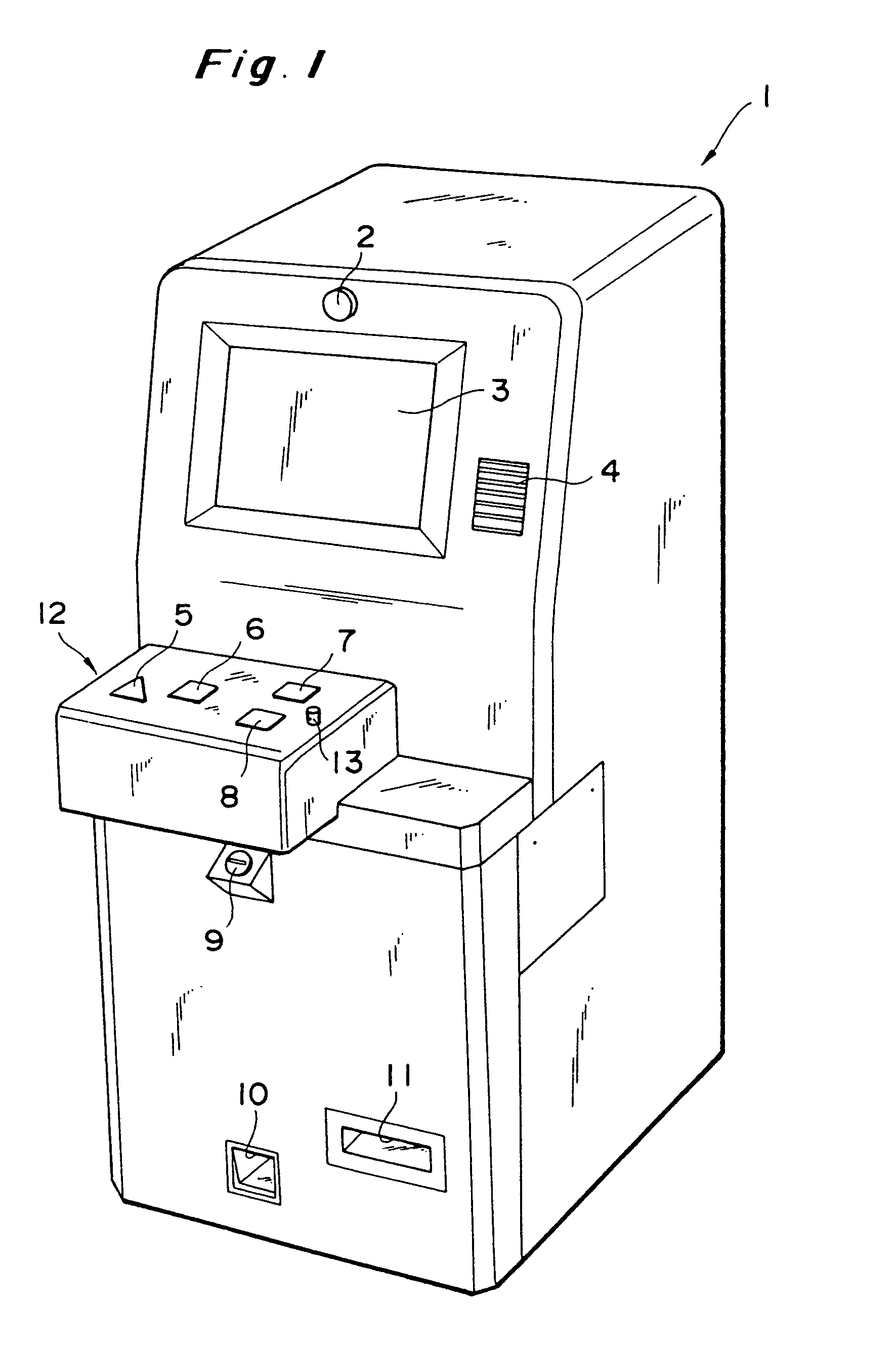
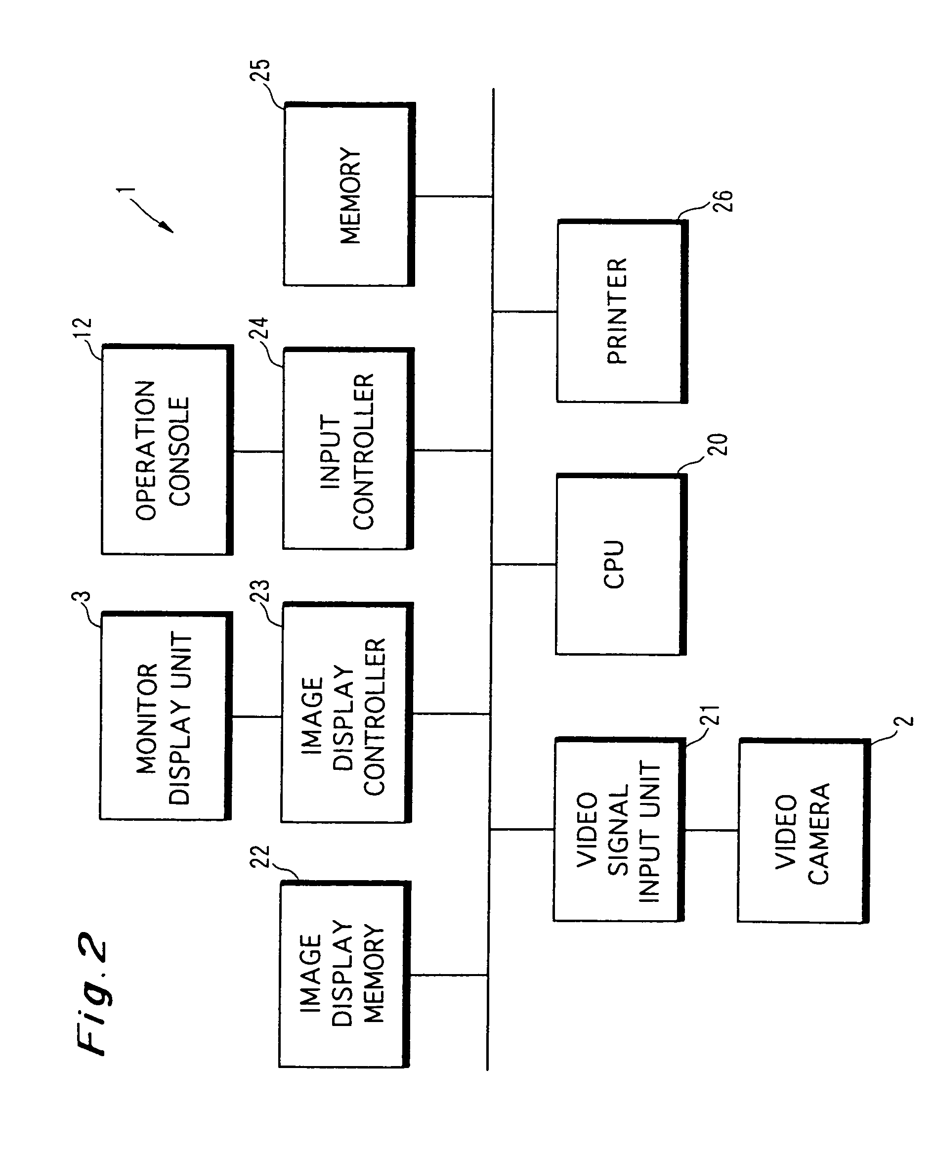
[0059]FIG. 1 is a perspective view of an image modification apparatus 1 according to an embodiment of the present invention.

[0060]The image modification apparatus 1 photographs the user (subject), modifies part of the image obtained by photography, displays the image and prints the image.

[0061]The image modification apparatus 1 has a front side the upper part of which is provided with a video camera 2 approximately at the center thereof. The user stands in front of the image modification apparatus 1 and faces the video camera 2, which captures the image of the user.

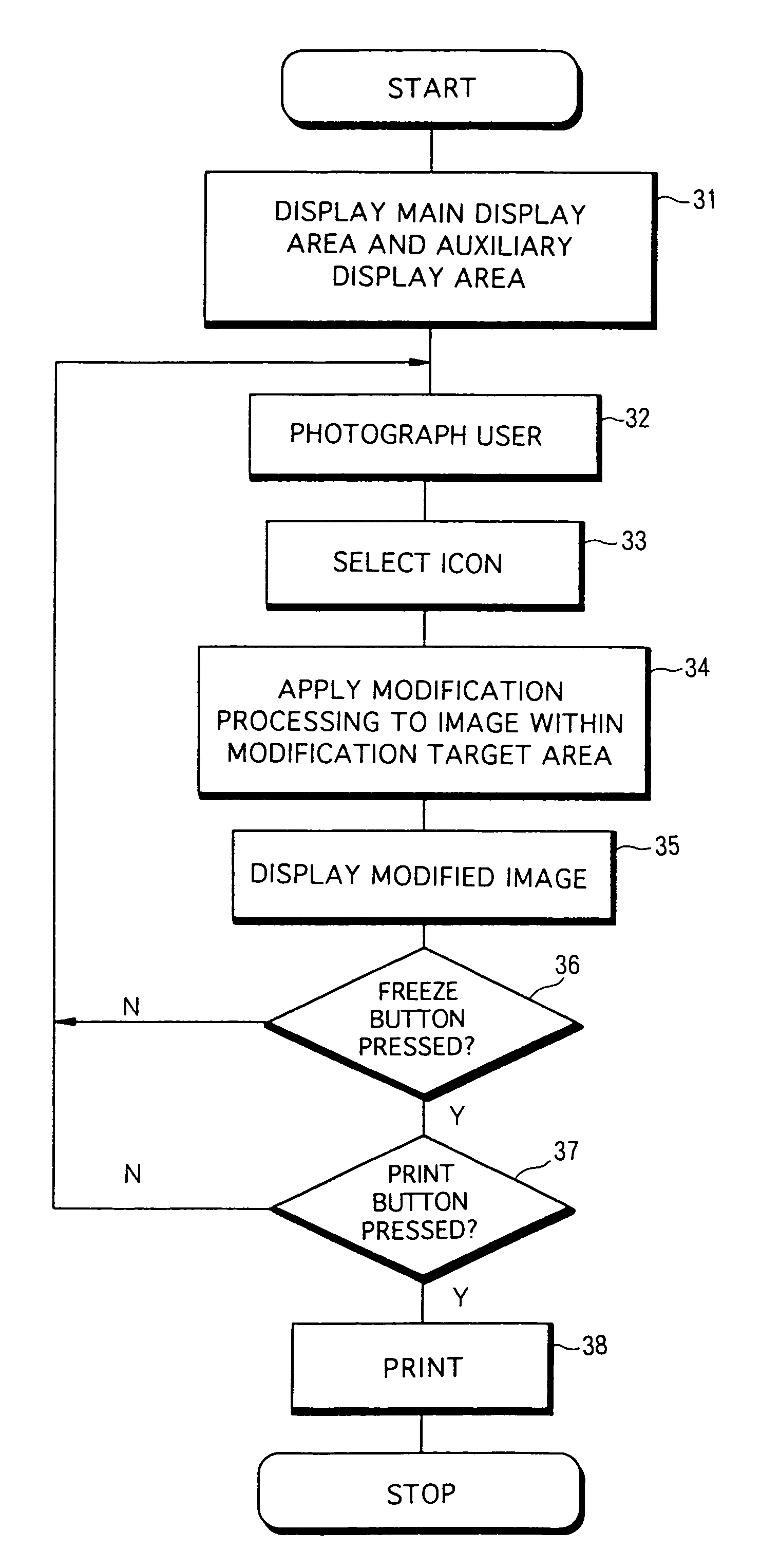
[0062]A monitor display unit 3 is provided below the video camera 2. The image of the subject captured by the video camera 2 is displayed as a moving picture on the display screen of the monitor display unit 3. (By pressing a freeze button 7, which is described below, a still picture of the subject image that was appearing on the screen when the button was pressed is displayed.)

[0063]A speaker 4 for outputting operation g...


PUM


Abstract

An individual not accustomed to operating a computer can obtain, with comparative ease, a modified image that is the result of modifying an image obtained by an image sensing operation. A subject is photographed by a video camera, and an image representing the subject is displayed in a main display area of a display unit. A modification target area is set in the main display area in advance, and icons representing methods of modification are displayed in an auxiliary display area. When one of these icons is selected, the image within the modification target area is modified by the selected modification method. If necessary, the user may move so that the portion of the subject image that the user wishes to be modified will fall within the modification target area.

Description

[0001]This application is a divisional of application Ser. No. 09 / 084,960, filed on May 27, 1998, now U.S. Pat No. 6,344,907 the entire contents of which are hereby incorporated by reference and for which priority is claimed under 35 U.S.C. § 120; and this application claims priority of application Ser. No. 9-158101 and 9-293217 filed in Japan on May 30, 1997 and Oct. 13, 1997, respectively under 35 U.S.C. § 119.BACKGROUND OF THE INVENTION[0002]1. Field of the Invention[0003]This invention relates to an apparatus and method for sensing the image of a subject, modifying the image of the subject obtained by such image sensing and displaying the modified image, as well as to a digital still-video camera, an image data recording method and an image modification method.[0004]2. Description of the Related Art[0005]Owing to advances in computer hardware and software, it has become possible to digitize displayed images such as photographs and input the digital images to a computer. It is al...

Claims


Application Information

Patent Timeline
Patent Type & Authority Patents(United States)
IPC IPC(8): G06K15/02H04N1/40G06F3/033G06F3/048G06T1/00G06T11/60G06T11/80H04N1/00H04N1/387
CPCG06F3/0481G06F3/04845G06T11/60H04N1/00286H04N1/00289H04N1/387
Inventor WATANABE, MIKIOHANEDA, NORIHISA
Owner FUJIFILM CORP
Learn More