Vibration proof mount device

a technology of vibration-proof mounting and mounting bracket, which is applied in the direction of shock absorber, jet propulsion mounting, machine support, etc., can solve the problems of increasing the number of assembly man-days, increasing the cost of the whole machine, and transferring vibrations of the power plant, so as to achieve a simple structure and less cost

Inactive Publication Date: 2005-08-04
KURASHIKI KAKO CO LTD
View PDF5 Cites 6 Cited by
  • Summary
  • Abstract
  • Description
  • Claims
  • Application Information

AI Technical Summary

Benefits of technology

[0015] In means adopted by the present invention for the purpose to achieve the object, a basic structure of a conventional known stopper mechanism is employed and, for example, a core body of a receiving member for a force in the vehicle body longitudinal direction such as a stopper rubber or the like is caused to revolve as if it were a link to thereby cause the receiving member for a force in the vehicle body longitudinal direction to be subjected to shear deformation in the vertical direction with comparative ease even when the receiving member receives a compressive force in the vehicle body longitudinal direction, thereby enabling a member of a vehicle body and a member of a power plant to displace relatively to each other in the vertical direction with comparative ease.
[0044] As described above, according to a vibration proof mount device related to the invention of the present application, in a case where an oscillation limiting device is provided instead of a torque rod as functional replacement in the vibration proof mount of a power plant mounted in a traverse mount fashion in an engine room of an automobile, a basic structure of a conventional known stopper mechanism is employed: for example with a core body in a receiving member for a force in the vehicle body longitudinal direction such as a stopper rubber so as to revolve around an axis in the vehicle traverse direction as if it were a link provided, the receiving member for a force in the vehicle body longitudinal direction is shear-deformed in the vertically direction with comparative ease when the receiving member receives a compressive force in the vehicle body longitudinal direction; therefore, not only can a load in the vehicle body longitudinal direction be received and absorbed with certainty as a torque rod does, though with a simple structure less in cost up, but also no dynamic spring constant suddenly increase in the vertical direction and the surrounding sound due to acceleration of automobile can be sufficiently suppressed.

Problems solved by technology

In a case where torque rods are provided to the main mounts in such a way as well, however, the number of parts constituting the mounts increases correspondingly to thereby raise the number of assembly man-days; therefore, leading to a problem to cause a lot of cost up.
Since, if the stopper rubber portions are, in such a way, brought into contact with the vehicle body, an adverse possibility arises that vibrations of the power plant are transmitted to the vehicle body side through the stopper rubber portion, stopper mechanisms described in Patent literatures 5 and 6 (JP No. 61-92329 A and JP No. 60-02541 B) each are equipped with the stopper rubber portion having protruded stripes at the distal end thereof or the stopper rubber portion having a hollow in the interior thereof, thereby reducing a stiffness thereof partly.
The conventional stopper mechanisms (disclosed in Patent literatures 3 to 6 and the like) each, however, have no function that an increase in dynamic spring constant in the vertical direction can be restricted to the lowest level without hindering upward and downward motions of a mount by receiving and absorbing a force in the vehicle body longitudinal direction acting on the mount as a torque rod acts, so the mechanisms each cannot be a substitute for the torque rod.
In acceleration of an automobile, for example, a power plant in the entirety, in some case, has great vibrations in the vertical direction because of unbalance in reciprocating inertia force or the like of the engine, when the power plant is inclined by a driving reaction force to thereby cause a stopper to act and to degrade vibration proof performance of mounts suddenly, which leads to an inconvenience that vibrations in the vertical direction accompanying the acceleration operation propagates into the vehicle compartment to generate a loud surrounding sound confined therein.

Method used


Image

  • Vibration proof mount device
  • Vibration proof mount device
  • Vibration proof mount device

Examples


embodiment 1

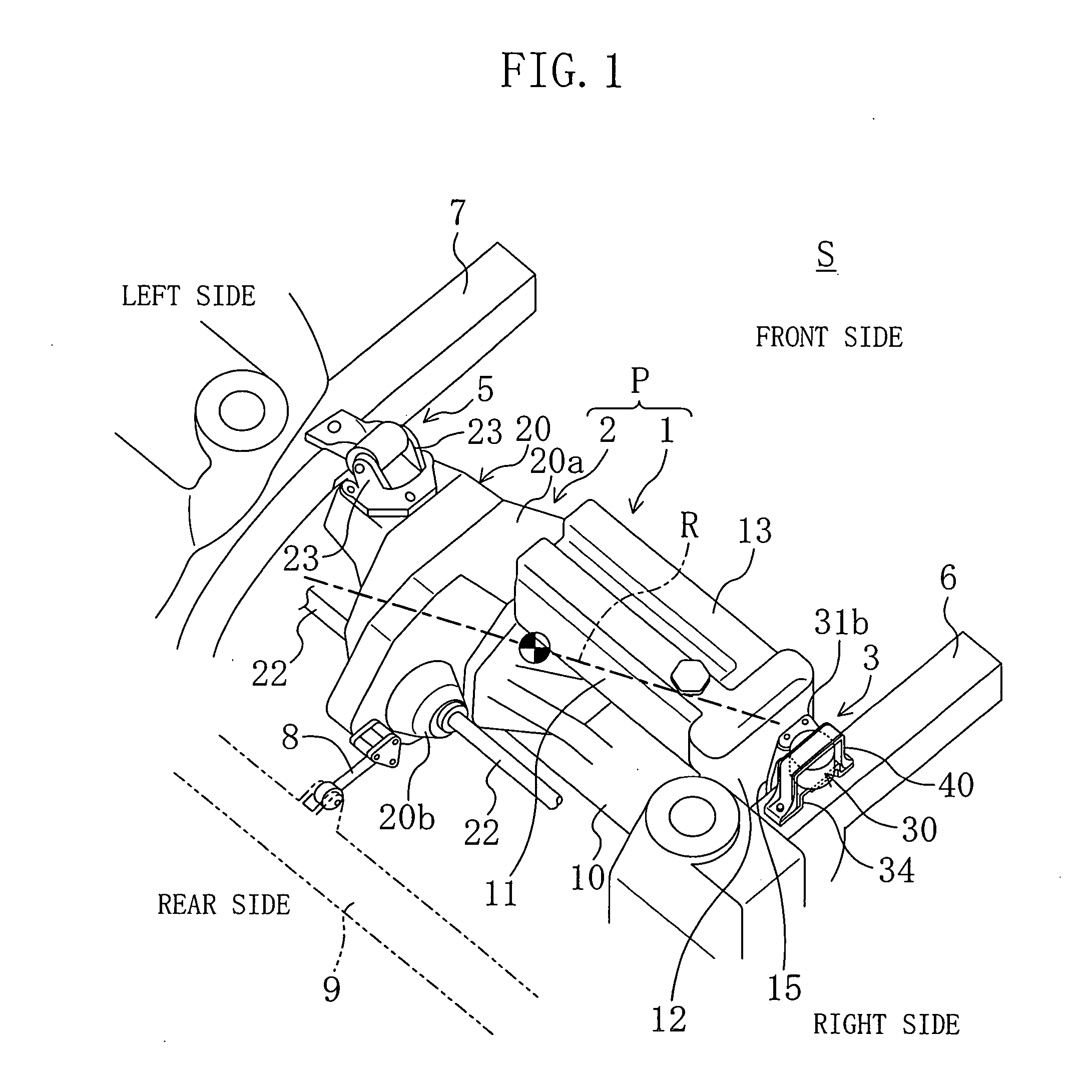
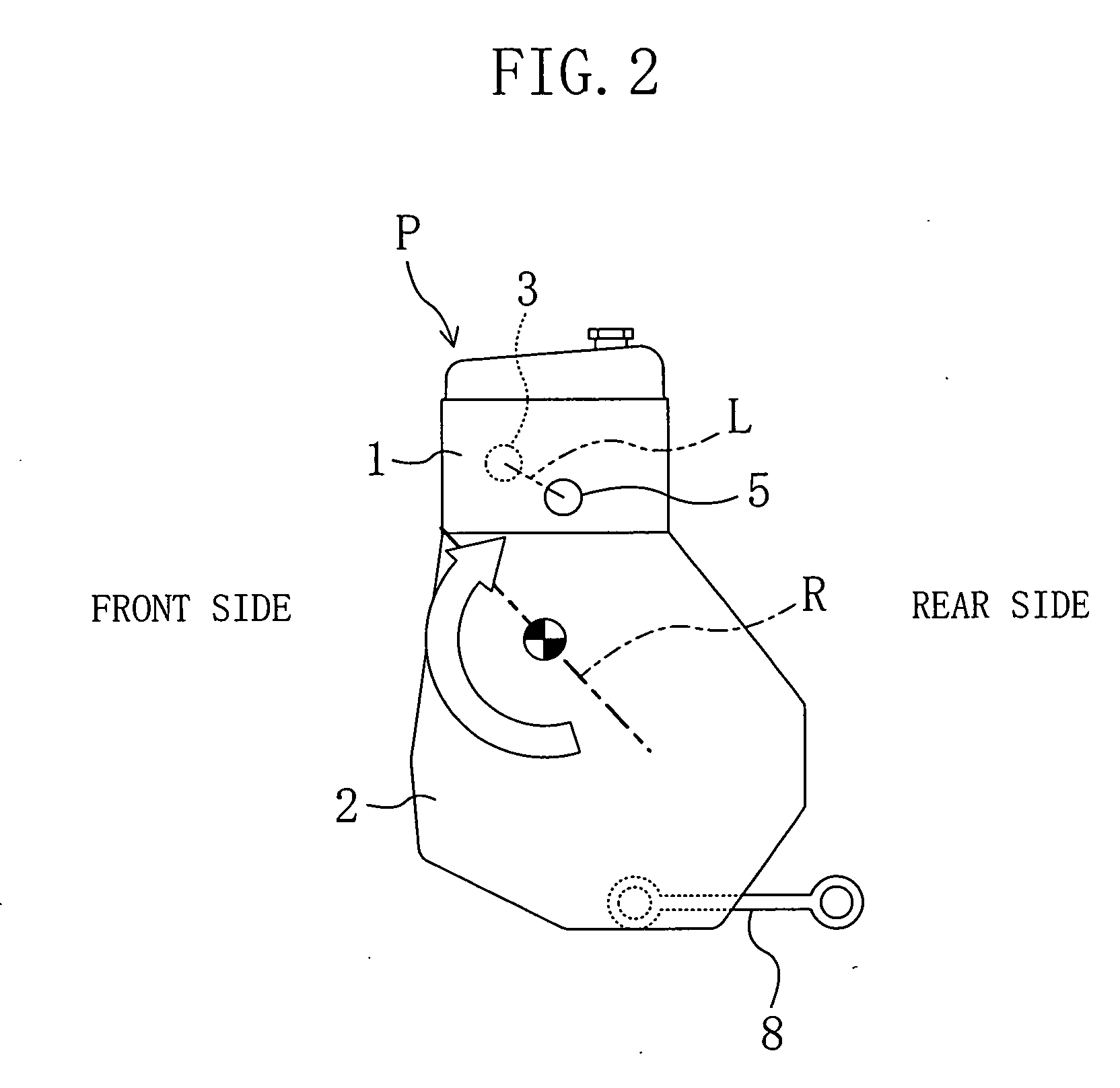
[0065]FIGS. 1 and 2 show a schematic construction of an engine mount system using a vibration proof mount device related to the embodiment 1 of the present invention. In both figures, a mark P is a power plant constructed by coupling in series an engine 1 and a transmission 2 to each other. The power plant P is mounted in an engine room of an automobile not shown in a traverse mount fashion so that the length direction thereof (a direction in which a crankshaft of the engine 1 extends) takes a vehicle width direction (a vehicle body traverse direction) and elastically supported by vehicle body side frames 6 and 7 at two sites thereof through mounts 3 and 5 disposed at both end portions in the length direction, that is at end portions on the side of the engine 1 thereof and the side of the transmission 2 thereof. The lower end portion of the power plant P is connected to a vehicle body side member 9 (a subframe or the like) in the rear side of the vehicle body by a torque rod 8 indep...

embodiment 2

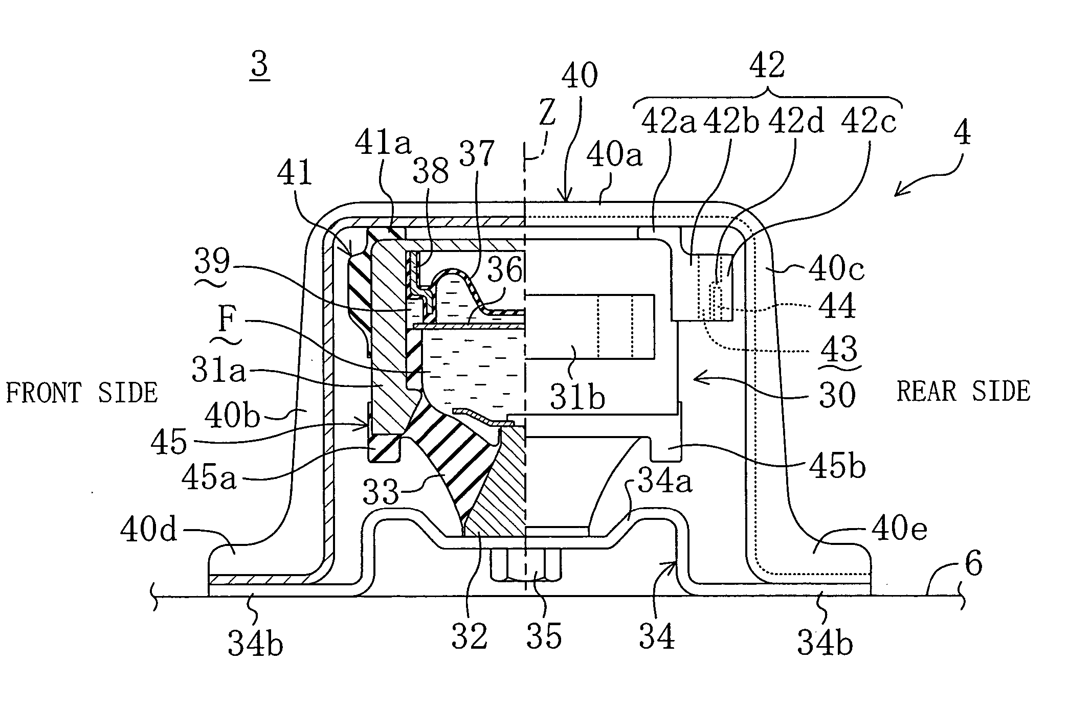
[0102] FIGS. 10 to 13 show an engine side mount 3 in the embodiment 2 of the invention of the present application. In the embodiment 2, as clear from the figures, no hollow portion 43 is provided in the rear side stopper rubber 42 of the oscillation limiting mechanism 4 and instead, a structure of the rubber portion in which the core portion is embedded is contrived so as to cause the core body 44 to perform a link action. Note that since a construction of the mount 3 in the embodiment 2 is the same as in the embodiment 1 except for details a structure of the rear side stopper rubber 42, the same marks are attached to the same constituents and descriptions thereof are omitted in the following passages of the specification.

[0103] Then, description will be detailed of a structure of the rear side stopper rubber 42 with reference to FIGS. 13A and 13B. The rubber portion of the rear side stopper rubber 42 is, as shown with a section in FIG. 13A, constructed from a connecting rubber por...

example modification

[0111] In the embodiment 2 as well, a shape of the core body 44 in the rear side stopper rubber 42 may not be in the shape of a rectangular plate and for example, may be in the shape of a crank in section as shown in FIG. 14A. A hollow portion 42d is formed in the interior of the rubber as shown in, for example, FIG. 14B instead of forming the rubber portions (the connecting rubber portion and the protruded portion) 42b and 42c before and after the core body 44 as shown in the FIGS. 14A and 13A shifted from each other in the vertical direction, and the centers of gravity of the rubber portions before and after the core body 44 or application points of forces in the rubber portions may be shifted from each other in the vertical direction.

[0112] As shown in FIGS. 14C and 14D, the core body 44 in the rear stopper rubber 42 is formed in the shape of a crank in section as viewed in the vehicle body traverse direction and the front end portion and rear end portion may be shifted in an of...


PUM


Abstract

An oscillation limiting mechanism 4 is integrally provided to an engine mount 3 (a vibration proof mount device) of a power plant P mounted on an automobile in a traverse mount fashion. Not only is a stopper metal member 40 in the shape of an inverted U letter disposed so as to cross over a mount body portion 30, but a stopper rubber 42 is formed so that it protrudes from the rear end of a casing of the mount body portion 30 toward the rear side of the vehicle body. Not only is a hollow portion 43 formed in the interior of the stopper rubber 42, but a metal core body 44 is also embedded in the stopper rubber 42 so as to be revolvable around an axis in the vehicle body traverse direction as if it were a link. With such a construction adopted, the stopper rubber 42 is shear-deformed in the vertical direction with comparative ease even in a state where it is brought into contact with the rear side leg portion 40c of a stopper metal member 40 and thereby receives a compressive force in the vehicle body longitudinal direction, and a dynamic spring constant of the mount 3 in the vertical direction does not rise so much even if the stopper acts in rapid acceleration or the like; therefore, enabling increase in surrounding sound in acceleration to be suppressed with a simple structure less of cost up while oscillation of the power plant P is limited in a similar way to that of a torque rod.

Description

BACKGROUND OF THE INVENTION [0001] The present invention relates to a vibration proof mount device for mounting a power plant on an automobile, and particularly, belongs to the technical field of a structure thereof in a case where a mechanism for limiting oscillation in a rolling direction of the power plant is installed integrally in a single body. [0002] In a front engine-front drive (FF) type vehicle, for example, generally a power plant has been conventionally mounted on the vehicle body with the length direction (a direction along which a crankshaft extends) thereof aligned in the width direction of the vehicle body so that both end portions thereof are elastically supported by the body side frames located on both sides, left and right, of the engine room (a so-called traverse mount type). [0003] As such a traverse mount type, main stream thereof is an inertia main axis mount scheme (or a torque roll axis scheme) in which main mounts on both ends, left and right, of the power ...

Claims


Application Information

Patent Timeline
Patent Type & Authority Applications(United States)
IPC IPC(8): F16F1/371F16F13/10
CPCF16F13/101F16F1/371
Inventor OHTA, KATSUTOSHIUCHIDA, SUMIOMIYAKE, TETSUYA
Owner KURASHIKI KAKO CO LTD
Why Eureka
Try Eureka