Vehicle seat assembly with biased headrest

a headrest and vehicle seat technology, applied in the direction of chairs, movable seats, transportation and packaging, etc., can solve the problems of occupants being forced against the seat, experiencing a very large energy pulse, and limiting the movement of the seat assembly,

Inactive Publication Date: 2007-04-10
LEAR CORP
View PDF33 Cites 30 Cited by
  • Summary
  • Abstract
  • Description
  • Claims
  • Application Information

AI Technical Summary

Benefits of technology

[0010]The headrest is automatically disengaged for movement relative to the seat back to thereby allow the seat back to move further when moving from an upright position to a stowed position. Also, the headrest automatically moves to and is engaged in the raised position when the seat back is moved from the stowed position to the upright position. The headrest does not need to be manually positioned like those of the prior art, and as such, the seat assembly is more convenient for the occupant and is more likely to properly support the occupant's thoracic, head, and neck region.

Problems solved by technology

In the event of a rearward impact, the occupant is forced against the seat and can experience a very large energy pulse.
This initial load may cause a separation between the seatback and the thoracic, neck, and head regions of the occupant.
In some cases, the headrest limits the movement of the seat assembly because the headrest interferes with the vehicle floor or other surrounding structure.
While seat assemblies with movable headrests of the prior art have functioned adequately for their intended purposes, certain problems still remain.
This can be an inconvenience for the occupant.
Also, the occupant may forget to manually raise the headrest, and as such, the headrest is unable to properly support the occupant's thoracic, neck, and head region in the event of a vehicular collision.

Method used


Image

  • Vehicle seat assembly with biased headrest
  • Vehicle seat assembly with biased headrest
  • Vehicle seat assembly with biased headrest

Examples


Embodiment Construction

)

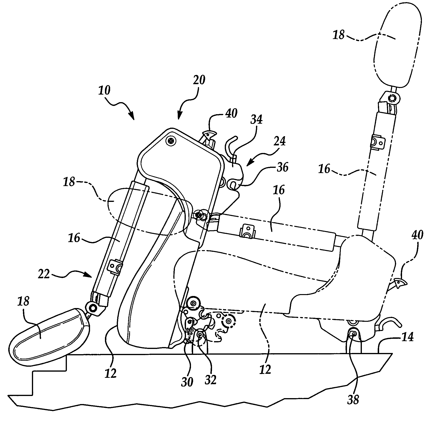
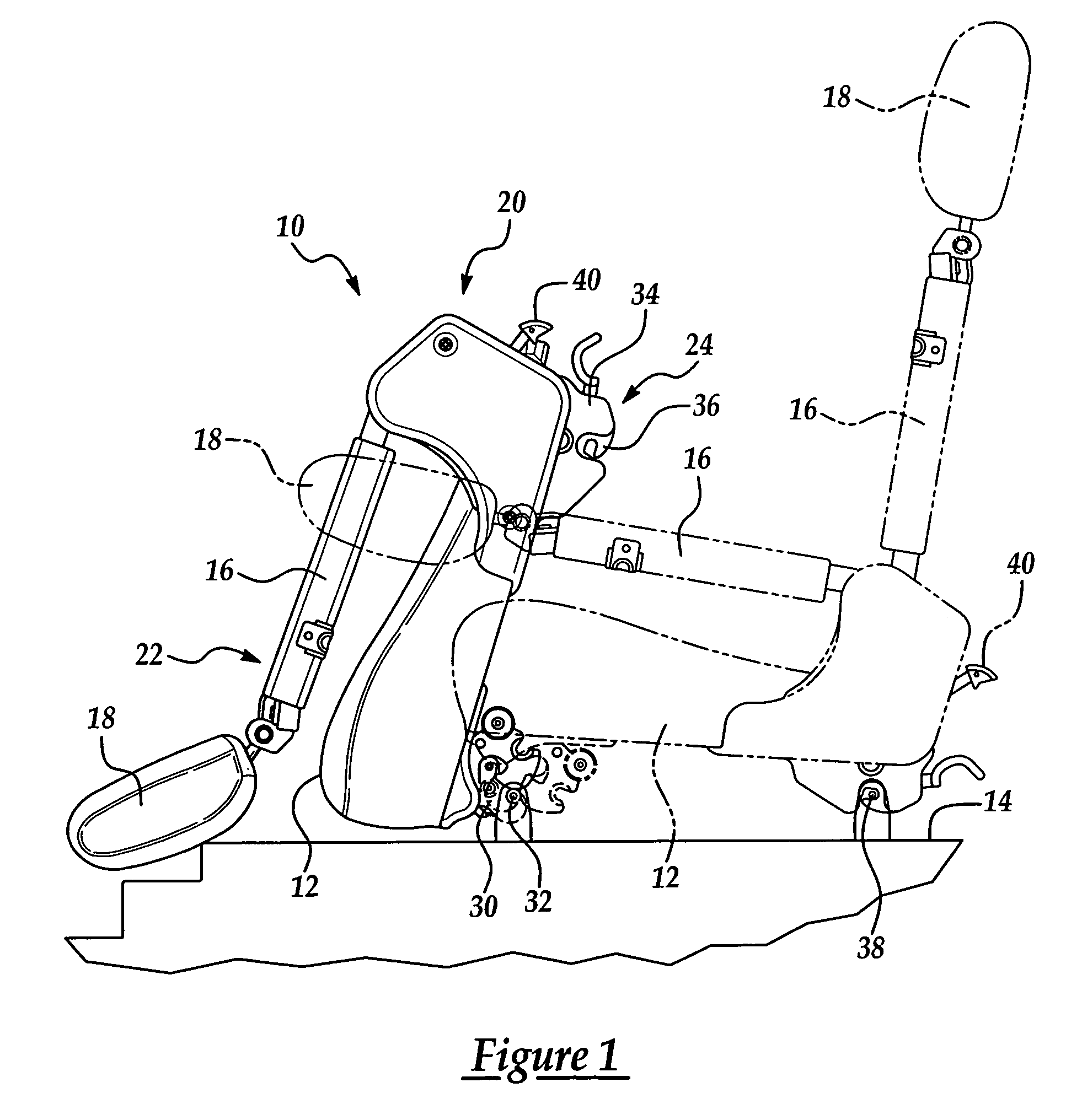
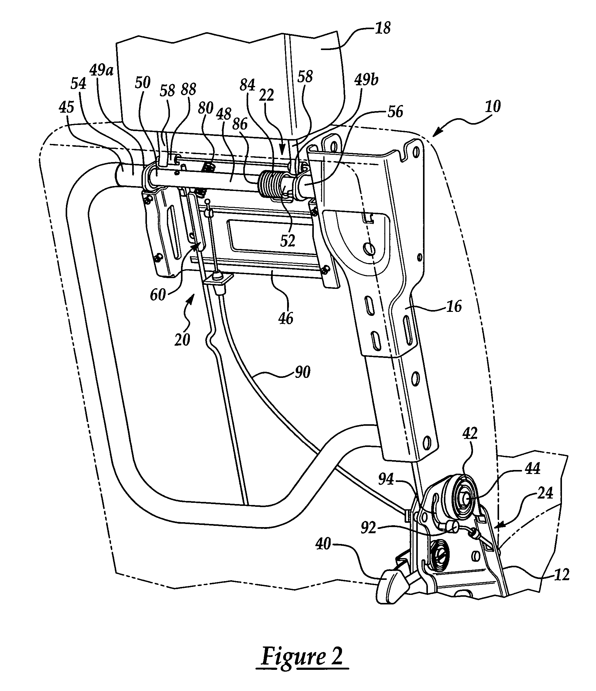
[0015]Referring now to the drawings, where like numerals are used to designate like structure throughout the figures, a vehicle seat assembly of the present invention is generally indicated at 10. As shown, the vehicle seat assembly 10 includes a lower seat cushion 12. The seat cushion 12 can include a soft cushioning material such as foam, a rigid frame, and a covering made out of fabric, leather, or the like. For purposes of clarity, the covering of the seat cushion 12 is shown in FIG. 1, but only the frame of the seat cushion 12 is shown in FIGS. 2 and 4. The seat cushion 12 is operatively supported by a vehicle floor 14, which is tiered in the embodiment shown. Also, the seat cushion 12 is supported for movement relative to the vehicle floor 14 in a manner to be described in greater detail below. In the embodiment shown, the seat cushion 12 can be positioned in a generally horizontal position so as to support an occupant thereon, and the seat cushion 12 can be rotated upward fr...


PUM


Abstract

A vehicle seat assembly including a lower seat cushion supported by the vehicle and a seat back supported for movement between an upright position and a stowed position. The seat assembly also has a headrest supported for movement relative to the seat back. A locking mechanism engages the headrest to retain the headrest in a raised position when the seat back is in the upright position. The locking mechanism also disengages the headrest for allowing movement of the headrest away from the raised position when the seat back is moved toward the stowed position. The seat assembly also has a biasing mechanism that biases the headrest toward the raised position.

Description

BACKGROUND OF THE INVENTION[0001]1. Field of the Invention[0002]The present invention relates, generally, to vehicle seat assemblies and, more particularly, to a vehicle seat assembly with a biased headrest.[0003]2. Description of the Related Art[0004]Conventional vehicle seat assembly designs typically include a seatback assembly, a lower seat cushion, a recliner mechanism, a manual or power adjustment mechanism for adjusting the position of either the seat back or seat cushion, as well as a number of safety features including occupant restraint devices such as seatbelts. The vehicle seat assembly also typically includes a headrest mounted at the top or upper end of the seat back.[0005]In the context of vehicle seating design, there is an ongoing effort to improve the safety of the vehicle occupant in the event of a collision. More specifically, there is an ongoing effort to provide safety mechanisms that reduce the chance of injury to the passenger's head and neck area. In the eve...

Claims


Application Information

Patent Timeline
Patent Type & Authority Patents(United States)
IPC IPC(8): A47C1/02B60N2/00
CPCB60N2/3011B60N2/305B60N2/4855B60N2/856
Inventor FREIJY, NIZAR
Owner LEAR CORP
Why Eureka
Try Eureka