Self-contained manual lifting screen

a self-contained, manual technology, applied in the direction of shutters/movable grilles, door/window protective devices, instruments, etc., can solve the problems of increased apparatus size and increased cost, and achieve the effect of little friction resistan

Inactive Publication Date: 2007-04-10
OS
View PDF13 Cites 28 Cited by
  • Summary
  • Abstract
  • Description
  • Claims
  • Application Information

AI Technical Summary

Benefits of technology

[0008]The screen can be smoothly and stably supported by the extension and retraction of the linking mechanisms disposed on the left and right sides when the screen is pulled upward (raised) and placed in the attitude of use, or when the screen is pushed downward and placed in an accommodated attitude. Furthermore, for example, if the right end or left end (with respect to the transverse direction of the screen) of the upper-end supporting member of the screen in the deployed state (use state) is pushed downward, or if the right end or left end (with respect to the transverse direction of the screen) of the upper-end supporting member of the screen in the accommodated state is pulled upward, the amounts of extension or retraction of the left and right linking mechanisms, i.e., the swinging angles of the left and right arms, will differ. As a result, the connected slide members cannot slide (move). In other words, unless the amounts of extension or retraction of the left and right linking mechanisms are the same, the extension and retraction actions of the linking mechanisms are forcibly stopped. In short, the raising or lowering of the screen can be accomplished by causing the left and right linking mechanisms to perform specified extension or retractions operations that are constantly determined, i.e., by always insuring that the swinging angles of the left and right arms are the same, so that the left and right linking mechanisms can be extended or retracted with good stability by the same integrally linked movements. Furthermore, it is conceivable that a large device such as a left-right balancing mechanism or the like could be attached in order to insure the stable extension and retraction of the let and right linking mechanisms; in such a case, however, the size of the apparatus would be increased, and the cost would also be increased. The extension and retraction operations of the left and right arms can always be regulated to the same movements merely by connecting two slide members installed on the left and right arms as in the present invention, so that the raising and lowering of the screen can be accomplished in a smooth manner.
[0010]Accordingly, if the attitude of the screen is switched from the use attitude to the accommodated attitude, the left and right arms, i.e., the left and right upper side arms, left and right lower side arms or both sets of left and right arms, are placed in a horizontal attitude, so that the left and right slide members that are free to move with respect to the arms contact the stopper members, thus making it possible to maintain the slide members in specified positions. As a result, in cases where the screen is switched from the accommodated attitude to the use attitude, the need to position the respective slide members in specified positions, i.e., the need to adjust the respective slide members to a state in which the connected positions of the slide members are located on a vertical line positioned in the approximate center of the screen with respect to the transverse direction of the screen, can be eliminated.
[0012]The abovementioned slide members consist of two split cases, and holding parts that are used to hold (in a manner that allows free rotation) head parts disposed on both ends of pins used to connect the split cases so that the split cases are capable of relative rotation are disposed on the respective split cases; as a result, the split cases can easily be mounted on the assembled linking mechanisms, and both split cases can be connected to each other by the pins in a manner that allows free relative rotation with little frictional resistance.

Problems solved by technology

Furthermore, it is conceivable that a large device such as a left-right balancing mechanism or the like could be attached in order to insure the stable extension and retraction of the let and right linking mechanisms; in such a case, however, the size of the apparatus would be increased, and the cost would also be increased.

Method used


Image

  • Self-contained manual lifting screen
  • Self-contained manual lifting screen
  • Self-contained manual lifting screen

Examples


Embodiment Construction

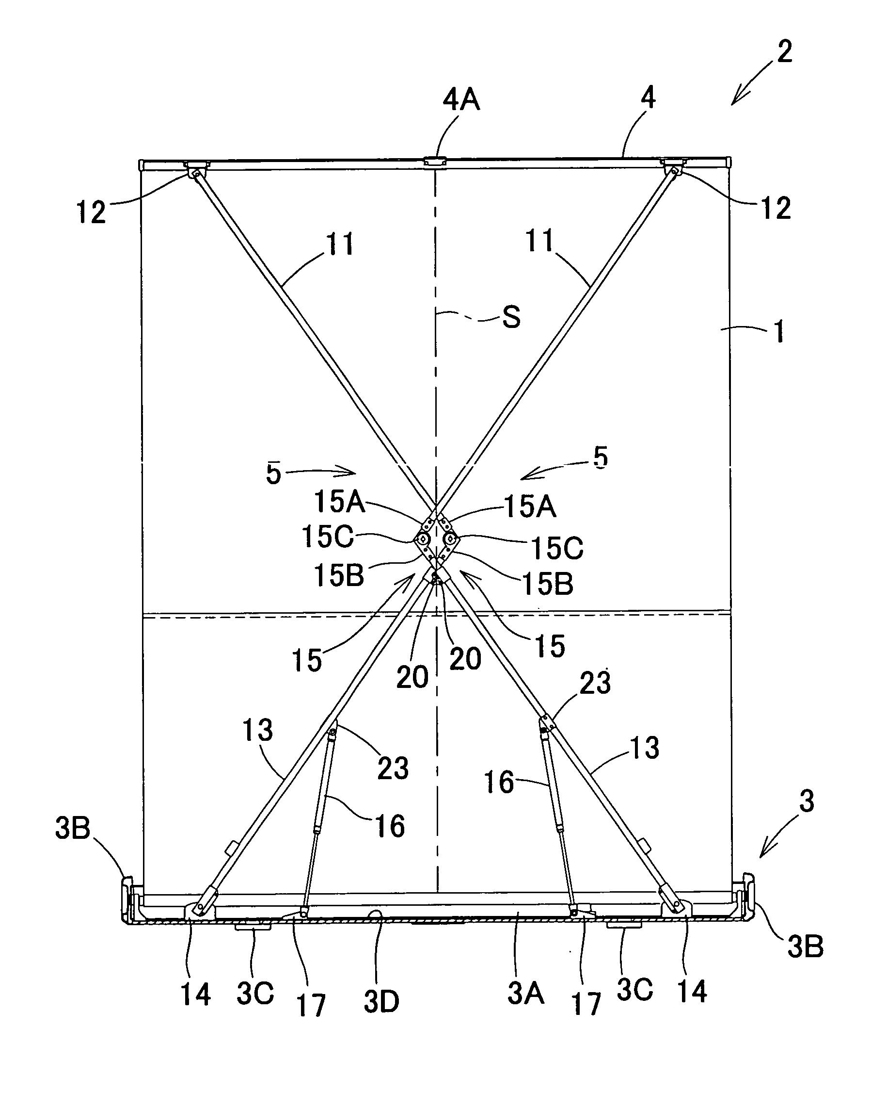
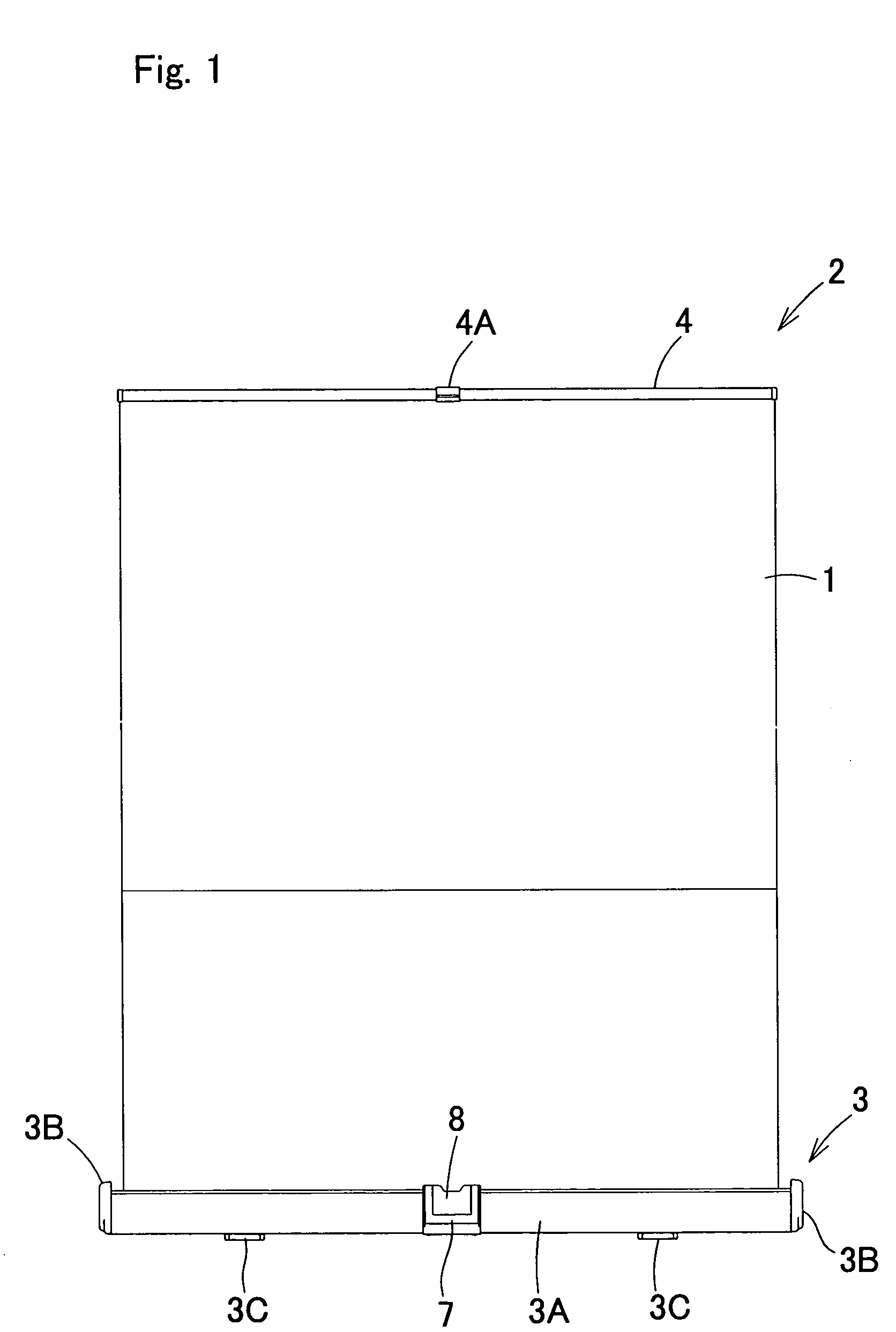
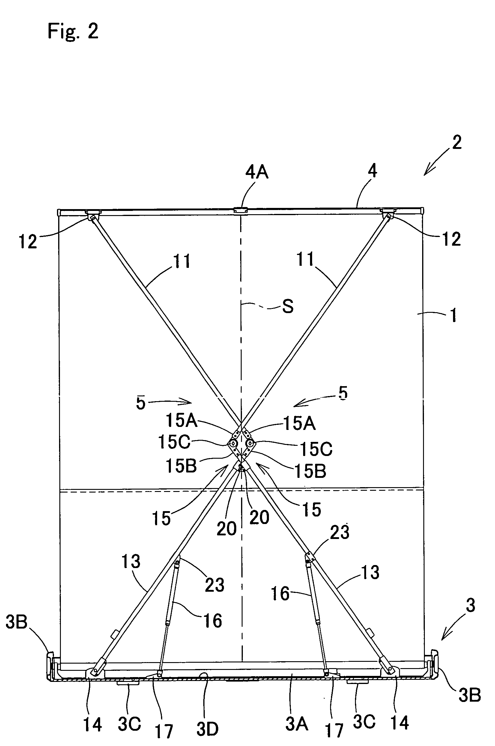
[0031]FIGS. 1 through 5 show a light-weight compact (handy type) self-standing accommodated elevating screen (hereafter referred to as a “elevating screen”) 2 in which the screen (the size of the screen may be a size other than that shown in the figures) 1 can be accommodated and carried. Furthermore, in the following description, the longitudinal direction of the casing 3 that is used to accommodate the elevating screen 2 shown in FIG. 1 (i.e., the width direction of the screen) will be taken as the transverse direction, and the direction perpendicular to the longitudinal direction of the abovementioned casing 3 (width direction of the screen) will be taken as the cross direction. The abovementioned elevating screen 2 comprises the abovementioned casing 3 which is used to take up and accommodate the abovementioned screen 1, and left and right linking mechanisms 5, 5 (see FIG. 5) which are disposed on the back the of the abovementioned screen 1, and whose upper ends are pivot-connec...


PUM


Abstract

It is an object of the present invention to provide a self-standing manually operated elevating screen which makes it possible to raise and lower the screen over a long period of time without encountering any trouble such as damage, deformation or the like, and which makes it possible to simplify the construction used for this purpose. The upper-end supporting member 4 to which one end of the screen 1 is connected and the base member 3D to which the other end of the screen 1 is connected are pivot-connected by left and right linking mechanisms 5, 5. Urging means 16, 16 which are used to urge the lower side arms 13, 13 upward are provided, and slide members 20, 20 that are free to slide are fit over either the let and right upper side arms 11, 11 or the left and right lower side arms 13, 13, or both. These left and right slide members 20, 20 are connected so that these members are free to rotate in relative terms on a vertical line S that is positioned in the approximate center of the screen 1 in the transverse direction of the screen.

Description

TECHNICAL FIELD[0001]The present invention relates to a self-standing manually operated elevating screen which is constructed so that the screen can be deployed upward by lifting an upper-end supporting member by hand, and so that the deployed screen can be taken up and accommodated inside a casing by pushing the upper-end supporting member downward, thus allowing the screen to be carried.BACKGROUND ART[0002]Various types of the abovementioned self-standing manually operated elevating screens have been proposed. For example, a system has been used in which the screen is held in a deployed position by pivot-connecting the upper end of a pantograph type linking mechanism to the approximate center of the upper-end supporting member of the screen with respect the transverse direction of the screen).[0003]However, in cases where the upper end of a linking mechanism is pivot-connected only to the approximate center of the upper-end supporting member of the screen with respect to the trans...

Claims


Application Information

Patent Timeline
Patent Type & Authority Patents(United States)
IPC IPC(8): G03B21/56E06B9/06G02B7/00G03B21/58A47G5/02F16M11/38G03B21/60
CPCF16M11/38G03B21/58F16M11/26F16M2200/063F16M2200/044F16M2200/061G03B21/60
Inventor KOTERA, MASAYUKI
Owner OS
Why Eureka
Try Eureka