Apparatus and method for calibration of a dispensing system

a technology of dispensing system and apparatus, which is applied in the field of calibration of dispensing system, can solve the problems of dispensing errors, large amount of calibration time wasted, and only available sensitive scales at a relatively high cos

Active Publication Date: 2007-04-17
ASM ASSEMBLY AUTOMATION LTD
View PDF20 Cites 14 Cited by
  • Summary
  • Abstract
  • Description
  • Claims
  • Application Information

AI Technical Summary

Benefits of technology

[0007]It is an object of the invention to seek to provide an improved apparatus and method for calibration of a dispensing system without some of the aforesaid disadvantages of the prior art.

Problems solved by technology

When small amounts of material are dispensed, such as to the order of 2 mg, such sensitive scales are only available at a relatively high cost.
Although weight can be converted into volume for a specific type of material, the specific gravity of polymeric material will vary in space, resulting in dispensing errors in addition to the errors inherent upon conversion.
This method is time-consuming, in that mechanical manipulation of the various devices during calibration results in the wastage of a large proportion of calibration time.
These steps of mechanical manipulation, including placement of a top pressure glass slide and plate by the dispensing system, locking using force rods, further compression of the plates with an air cylinder and finally the measurement by a viewing system are complicated.
Thus, productivity lost from increased operation time of the dispensing device.
A further problem with the above prior art dispensing systems is that they are limited to calibration of a dispenser adapted for dot dispensing.
Other modes of dispensation, such as line dispensing cannot be properly simulated and worked using this tool.
Thus, the above methods do not provide an optimal solution to dispensing system calibration in a real environment.

Method used


Image

  • Apparatus and method for calibration of a dispensing system
  • Apparatus and method for calibration of a dispensing system
  • Apparatus and method for calibration of a dispensing system

Examples


Embodiment Construction

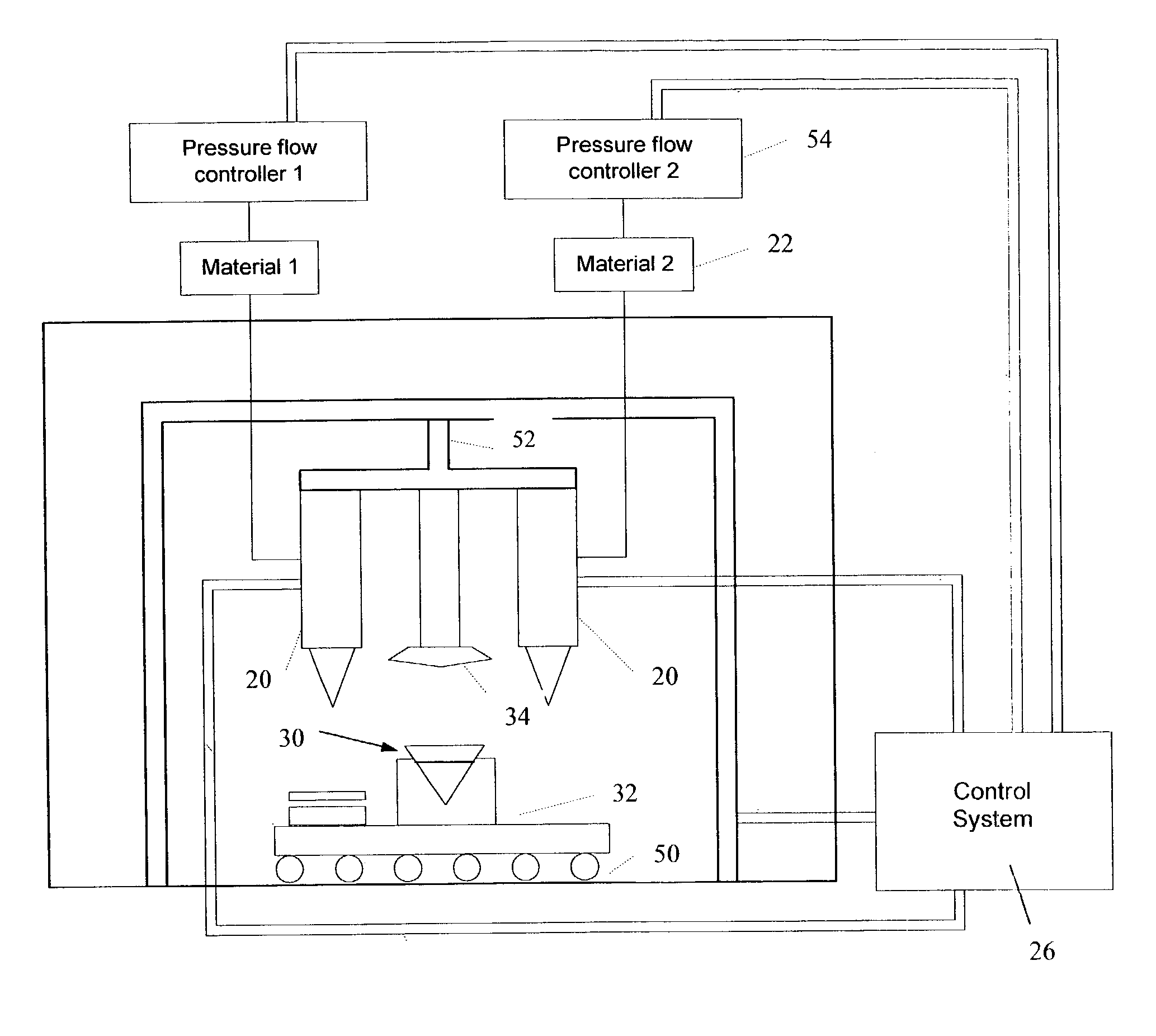
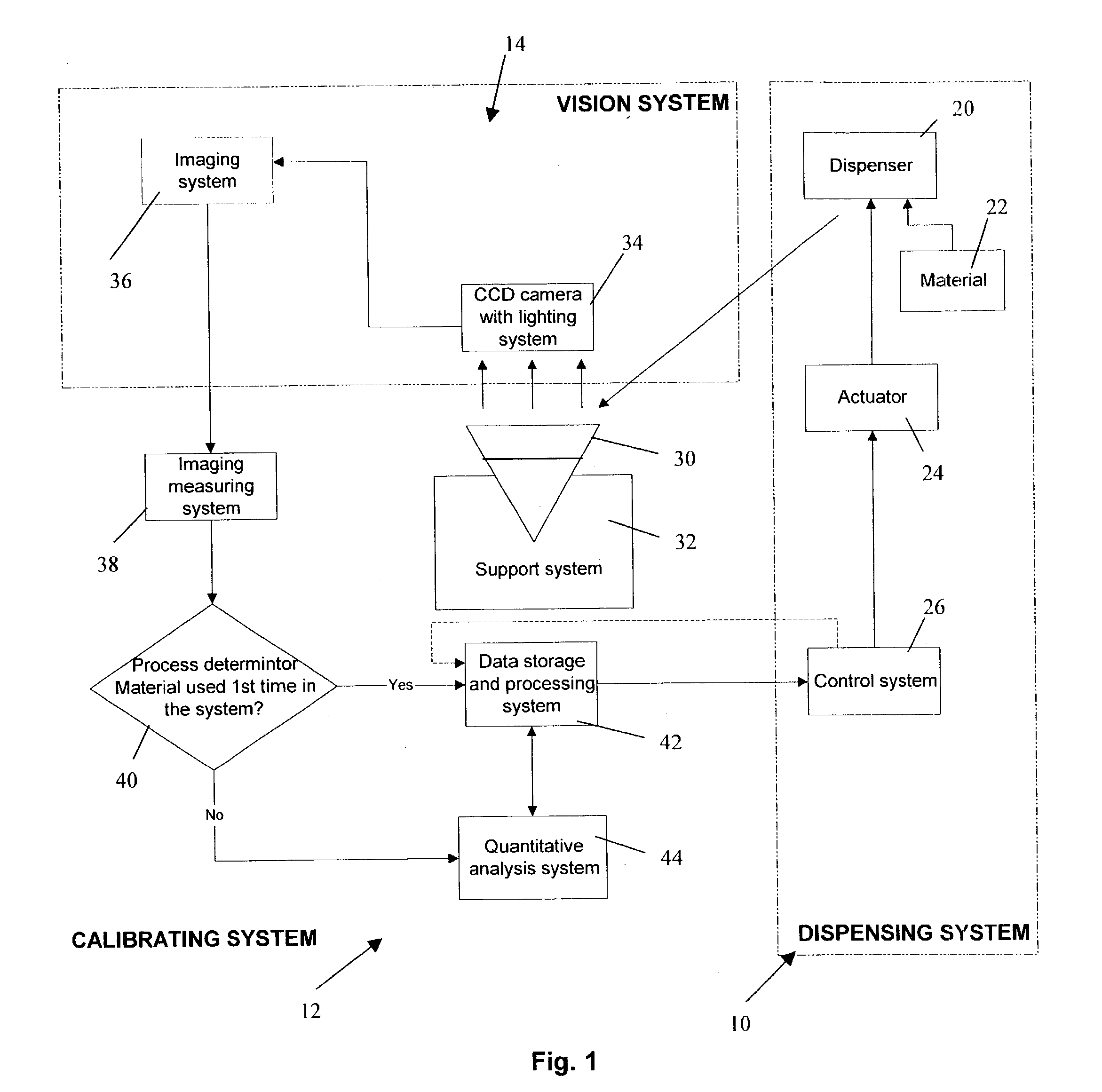
[0019]FIG. 1 is a schematic illustration of the relationship between a dispensing system 10, calibrating system 12 and vision system 14 according to a preferred embodiment of the invention. The dispensing system 10 includes a dispenser 20 for dispensing a controlled quantity of material 22 onto a substrate such as a printed circuit board. An actuator 24 induces flow of material 22 using pressure valves or other mechanisms. These mechanisms are monitored and adjusted with a computerized control system 26, so that the dispenser 20 may extrude a stable and controlled volume of material 22 based upon feedback. Flow-rates from the dispenser 20 may be automatically controlled using the control system 26. Although the invention may be implemented with more than one dispenser 20, only one dispenser 20 is illustrated in FIG. 1 for simplicity.

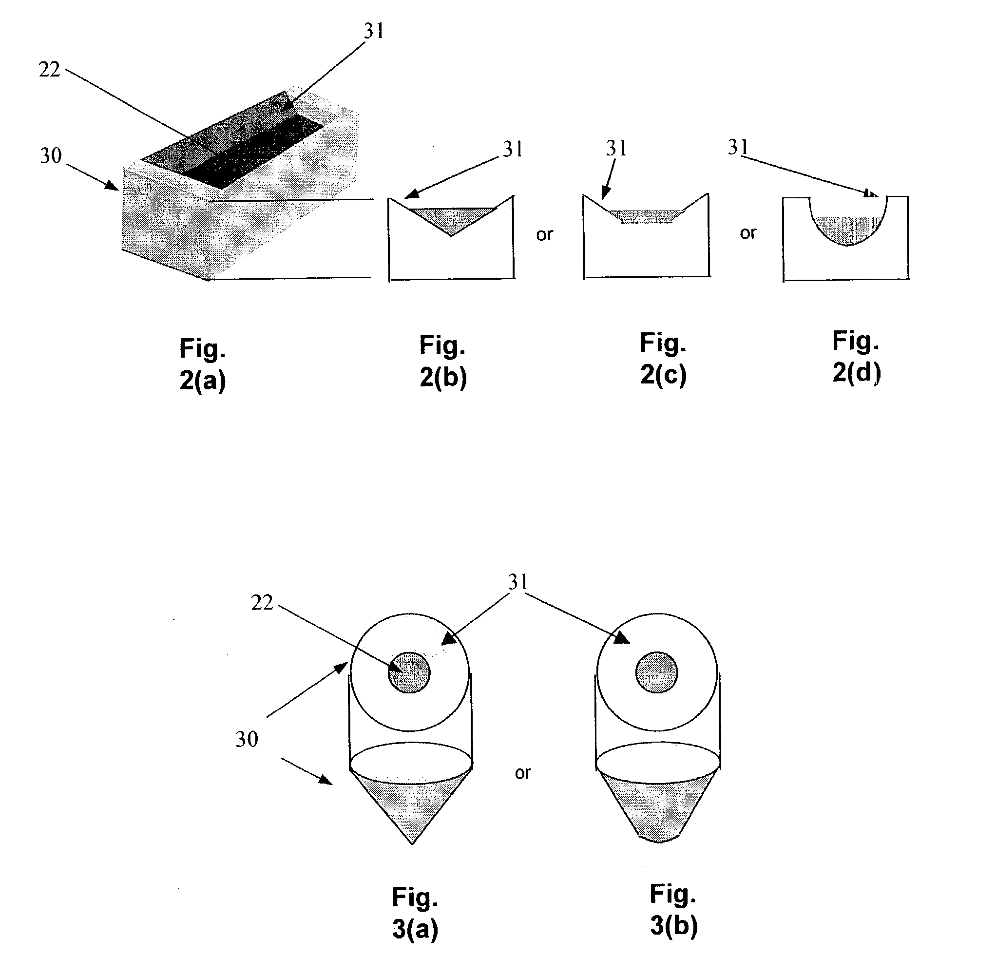
[0020]During calibration, the dispenser 20 extrudes a quantity of material 22 such as underfill or fill material into a material-receiving cavity of a s...


PUM

PropertyMeasurementUnit
timeaaaaaaaaaa
physical dimensionaaaaaaaaaa
volumeaaaaaaaaaa

Abstract

The invention provides an apparatus and method for calibrating a dispensing system. A dispenser dispenses a controlled quantity of material into a container for receiving material. A system, preferably a vision system comprising an image capturing device and an imaging system, is adapted to capture an image of a physical dimension of a quantity of dispensed material in a given time. The physical dimension may be a width of a top surface area, a height or a cross-sectional area of the dispensed material. A calibrating system is adapted to calculate a volume of the quantity of material based upon said physical dimension.

Description

FIELD OF THE INVENTION[0001]The invention relates to dispensing systems used in the semiconductor industry, and in particular, to the calibration of dispensing systems for more accurate and precise dispensation of material from dispensers.BACKGROUND AND PRIOR ART[0002]Dispensing systems are used widely in the semiconductor industry for a range of applications. These applications include underfill processes, encapsulation and dispensing of adhesive substances onto circuit boards for mounting components. Accuracy and precision of dispensing is becoming more important because sizes of semiconductor packages are gradually decreasing. In addition, automated measurement and adjustment of dispensed quantities with computerized control systems is becoming the norm to reduce human intervention and increase speed. As a result, accurate automated calibration systems are required.[0003]For example, U.S. Pat. No. 5,906,682 for a “Flip Chip Underfill System and Method” discloses a calibration sys...

Claims


Application Information

Patent Timeline
Patent Type & Authority Patents(United States)
IPC IPC(8): B01L3/02B32B5/02G01F19/00G01N21/00G01N31/00G01F11/00G01F25/00G01N35/10H01L21/00
CPCG01F11/006G01F25/0084H01L21/67126H01L21/67253B01L3/0241Y10T436/2575Y10T436/10G01N35/1016
Inventor HUI, HON CHIULAM, WING FAIKONG, LIM PUNMAK, KA YEELEE, KA YIN
Owner ASM ASSEMBLY AUTOMATION LTD
Why Eureka
Try Eureka