Method for designing a blower wheel scroll cage

a technology of a blower wheel and a shape, applied in ventilation systems, heating types, instruments, etc., can solve problems such as difficult design of air systems for window unit room air conditioners

Inactive Publication Date: 2007-04-17
WHIRLPOOL CORP
View PDF13 Cites 11 Cited by
  • Summary
  • Abstract
  • Description
  • Claims
  • Application Information

AI Technical Summary

Problems solved by technology

Air systems for window unit room air conditioners are difficult to design due to the compact size of the cabinet.

Method used


Image

  • Method for designing a blower wheel scroll cage
  • Method for designing a blower wheel scroll cage
  • Method for designing a blower wheel scroll cage

Examples


Embodiment Construction

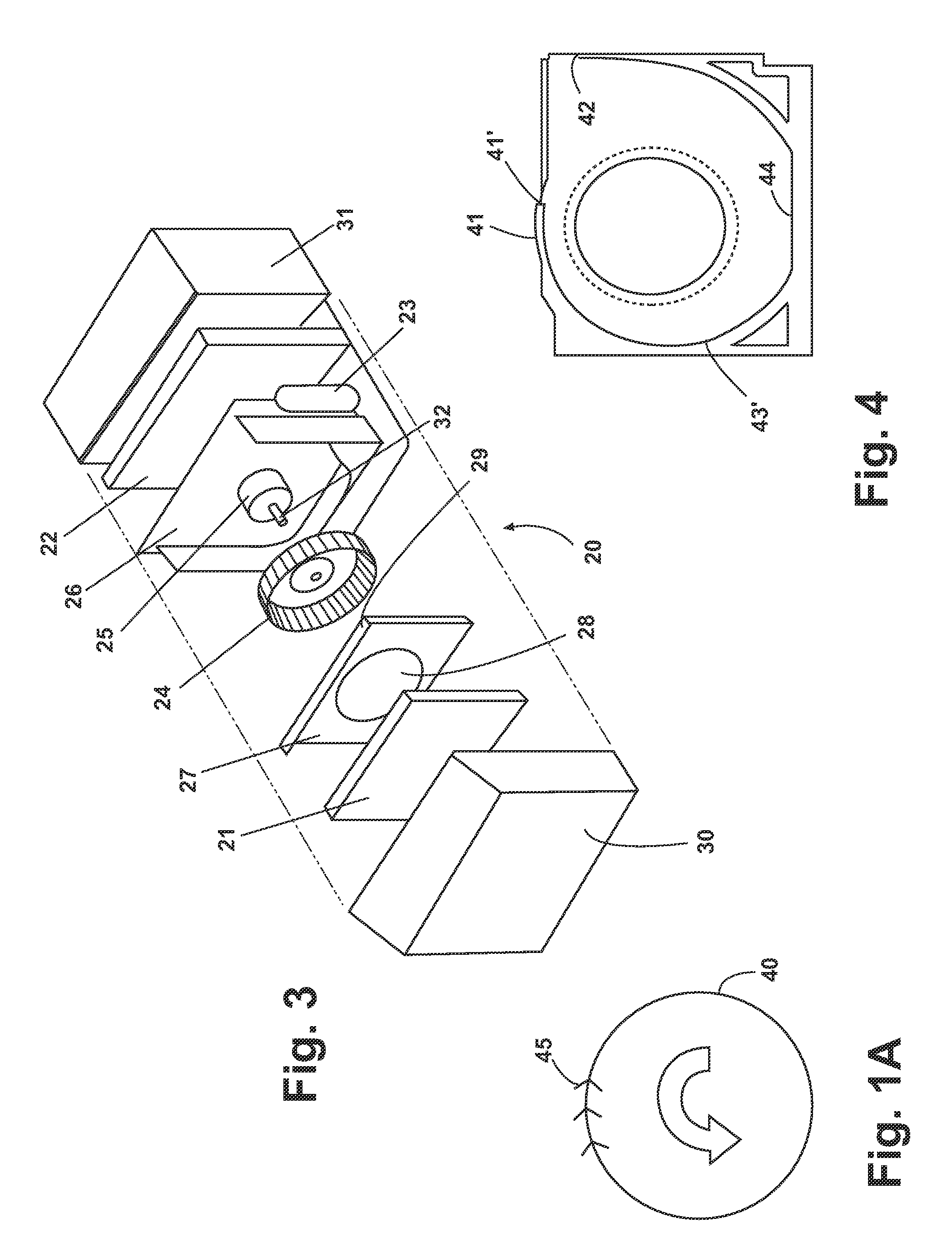
[0017]Air system design objectives for blowers applied to products such as a room air conditioner can include low noise and high air system efficiency with smooth air distribution and compact size utilizing a full development scroll. A forward-curved centrifugal drum-like blower wheel can satisfy air system design objectives for a room air conditioner. However, the configuration of the scroll cage and blower housing for a forward-curved centrifugal drum-like blower wheel significantly affects the air system performance. FIG. 1A shows, in schematic form, a forward-curved centrifugal blower wheel 40 having blades 45 curved forwardly relative to the direction of rotation shown by arrow 46. Those skilled in the art will recognize that blades 45 extend around the entire periphery of the blower wheel 40, and that the actual shape of the forward-curved blades 45 can be designed to achieve desired blower wheel performance as is well known in the art. If the profile of the scroll cage is not...


PUM


Abstract

A method for determining the shape of a scroll cage for a forward-curved centrifugal blower wheel in a blower housing having a blower cut-off end including determining the blower wheel dimensions, determining the blower wheel clearance, determining the distance from the center of the blower wheel to the discharge point of the scroll cage at the tangential point of the scroll cage and the blower housing, selecting a diffusing angle, calculating a development angle and plotting the scroll cage profile in polar coordinates. The method can include iteratively adjusting the diffusing angle and re-plotting the scroll cage profile and running simulations to determine the optimum profile.

Description

BACKGROUND OF THE INVENTION[0001]1. Field of the Invention[0002]The invention relates to a method for determining the shape of a blower wheel scroll cage. One application for such a blower wheel scroll cage is for a room air conditioner.[0003]2. Description of the Related Art[0004]Centrifugal blowers having a scroll cage are known for use in air handling devices including room air conditioners. Air systems for window unit room air conditioners are difficult to design due to the compact size of the cabinet. The air system of a room air conditioner having a centrifugal blower wheel can consist of two portions the scroll cage and the discharge hood.SUMMARY OF THE INVENTION[0005]One embodiment of the invention is a method for determining the shape of a scroll cage for a forward-curved centrifugal blower wheel in a blower housing having a blower cut-off end. The method according to the invention includes the steps of: determine the blower wheel dimensions (Rwheel×blower wheel depth); cal...

Claims


Application Information

Patent Timeline
Patent Type & Authority Patents(United States)
IPC IPC(8): G06F17/50F04D29/40F04D27/00F04D29/42F24F7/007G06F19/00
CPCF04D27/001F04D29/4206F24F7/007F04D29/4226F04D29/441F05D2250/52
Inventor CHEN, YUQI
Owner WHIRLPOOL CORP
Why Eureka
Try Eureka