Dead locking deadbolt

a deadbolt and locking technology, applied in the field of deadbolts, can solve the problem that the deadbolt cannot be operated by a key, and achieve the effect of reliable and simple us

Active Publication Date: 2007-04-24
MASTER LOCK CO INC
View PDF37 Cites 29 Cited by
  • Summary
  • Abstract
  • Description
  • Claims
  • Application Information

AI Technical Summary

Benefits of technology

[0008]The invention provides a lock-out device for a locking mechanism that is reliable and simple to use and, in some embodiments, signals to the user that the lock-out mechanism has been activated. The invention may be comprised of a shaft upon which a knob or handle is mounted that has openings or channels in the wall of the shaft. The openings in the shaft correspond to protrusions or protuberances in the shaft housing. To operate the lock-out device, when the knob is turned to the locked position in which the deadbolt is extended, the handle or knob may be pulled which pulls the openings in the shaft into interlocking engagement with the protrusions in the shaft housing. As a result, a mechanical member that operates the locking mechanism is restrained, thus “locking out” the deadbolt bolt mechanism. Thus, the deadbolt can not be operated by a key through a key cylinder mounted on the exterior side of the door effecting a “lock-out” condition. In some embodiments, when the shaft is pulled into a lock-out position, a portion of the shaft becomes visible from the interior-side of the door. In some embodiments the visible portion of the shaft includes an indicator or warning mechanism to signal to the user that the deadbolt is now in “lock-out” condition.

Problems solved by technology

Thus, the deadbolt can not be operated by a key through a key cylinder mounted on the exterior side of the door effecting a “lock-out” condition.

Method used


Image

  • Dead locking deadbolt
  • Dead locking deadbolt
  • Dead locking deadbolt

Examples


Embodiment Construction

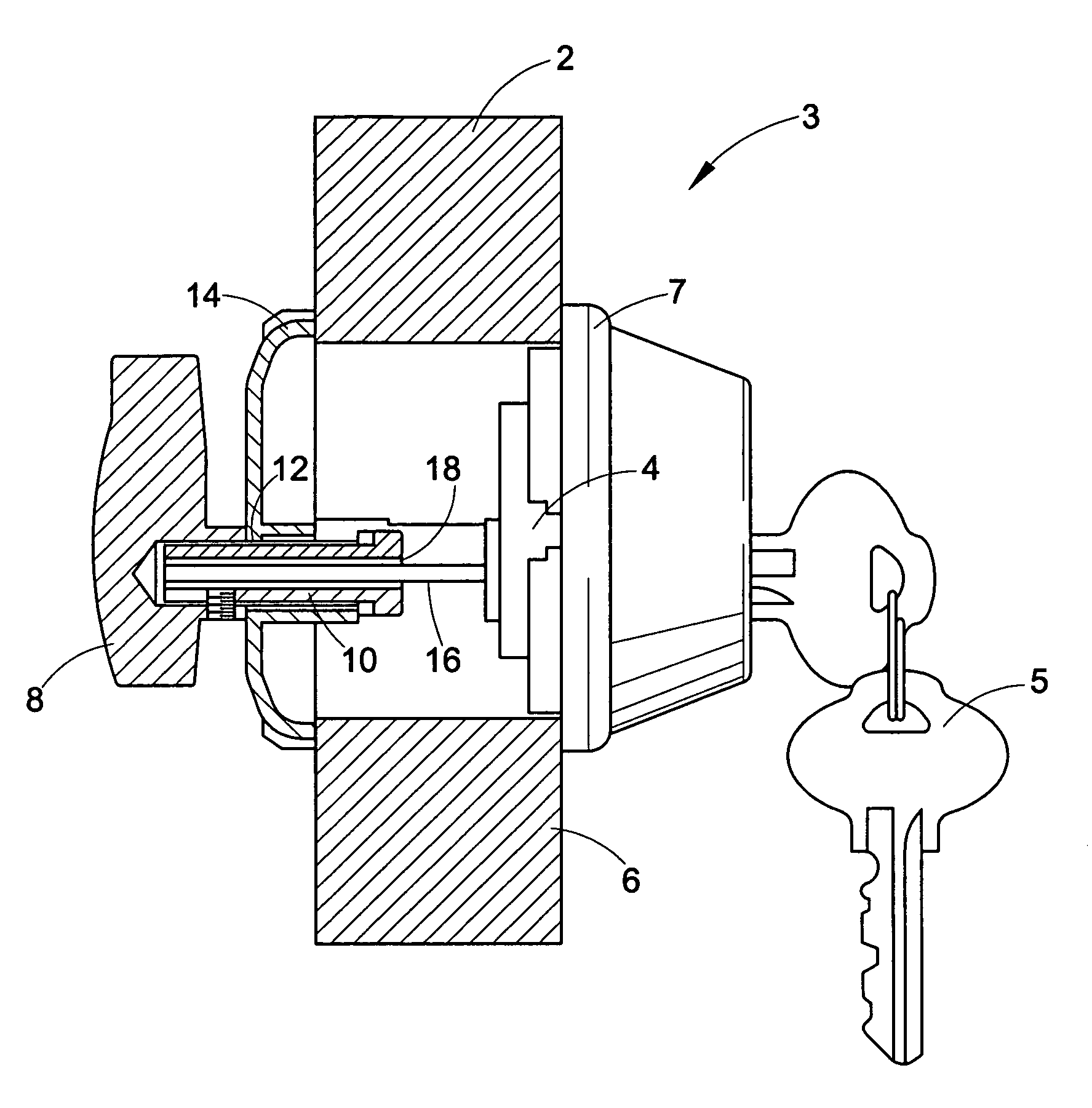
[0029]Referring now to FIG. 1, a door 2 including one embodiment of the invention is shown. As can be seen, a deadbolt manipulation mechanism, such as a conventional key cylinder 4 is mounted on one side of the door 2 which permits the deadbolt mechanism 3 to be operated by a key 5. The key cylinder 4 is normally mounted on the exterior side 6 of the door 2 in a protective housing 7. The “exterior-side” of a door is the side which is on the outside wall of a dwelling or building or any space desired to be “locked” from unauthorized entry. However, this invention is not limited to such a configuration and the key cylinder may be mounted on the interior or exterior side of the door. A second deadbolt manipulation mechanism, such as a knob or handle 8 also for operating the deadbolt is mounted on the side of the door opposite the key cylinder 4. The knob or handle 8 is mounted on a shaft 10 further described below. The shaft 10 is, in turn, mounted in an opening 12 in a shaft housing 1...


PUM


Abstract

A deadbolt mechanism including a lock out mechanism that functions to disable the operation of the deadbolt from at least one side of the deadbolt mechanism. The deadbolt mechanism includes a deadbolt, key cylinder, housing, turn knob and a shaft that connects the key cylinder and turn knob. To place the deadbolt mechanism in lock out mode, the turn knob is moved to the locked positioned and then pulled outward away from the door. By pulling the knob outward, the shaft engages a portion of the housing which prevents rotation of the shaft and thereby prevents movement of the deadbolt from the locked position.

Description

CROSS REFERENCE TO RELATED APPLICATIONS[0001]This application claims the benefit under 35 U.S.C. §119(e) of U.S. Provisional Application Ser. No. 60 / 481,268 filed Aug. 20, 2003, the entire disclosure of which is hereby incorporated by reference.BACKGROUND OF INVENTION[0002]This invention relates to locking devices in general and “lock-out” devices for deadbolts in particular.[0003]Bolts or deadbolts are well known devices for locking a door shut for security purposes. In such well-known arrangements, the deadbolt or bolt is mounted in the body of the door and the deadbolt is operated by mechanical operating devices mounted on either side of the door. When the deadbolt is operated to a locked position it typically extends or projects from the side of the door into an opening in the door jam or wall to which the door is mounted. Thus, the deadbolt when operated to an extended position, “bolts” or “locks” the door in a closed position. The mechanical operating devices also can operate ...

Claims


Application Information

Patent Timeline
Patent Type & Authority Patents(United States)
IPC IPC(8): E05B65/06E05BE05B13/00E05B17/04E05B41/00E05B63/14E05C1/06E05C1/14
CPCE05B13/00E05B13/004Y10T292/1028Y10T70/5341Y10T70/7915Y10T70/5465Y10T292/96Y10T292/57Y10T70/5394Y10T70/5513Y10T70/546Y10T70/8027
Inventor SMITH, JERRYENSLOW, MIKE
Owner MASTER LOCK CO INC
Why Eureka
Try Eureka