
Firearm projectile

a projectile and projectile technology, applied in the field of firearm projectiles or bullets, can solve the problems of bullets being deflected from their true path, reducing muzzle velocity, and reducing the effective range of more modern center fire rifles and the speed of reloading available to cartridge firearms

Active Publication Date: 2007-04-24
THOR INC
View PDF14 Cites 9 Cited by
  • Summary
  • Abstract
  • Description
  • Claims
  • Application Information

AI Technical Summary

Benefits of technology

"The patent describes a new type of bullet for a firearm that is designed to fit a specific caliber of firearm. The bullet has a small size and includes a hollow recess called a counter bore. The walls of the counter bore are shaped to make limited contact with the firearm during loading and to make good contact with the firearm during firing. The bullet also has an expansion plug that is placed inside the counter bore and is designed to move and expand during firing, which helps to push the walls of the counter bore outward and improve contact with the firearm. The new design of the bullet helps to improve the performance and accuracy of the firearm."

Problems solved by technology

The muzzleloader is essentially a primitive rifle, shotgun, or pistol, based on designs used during the early days of America and lacking the effective range of more modern center fire rifles and the speed of reloading available to cartridge firearms.
Further, the time it takes to reload a muzzleloader generally means that the hunter gets only a single shot at a target requiring them to be sure of their aim before firing, or to track moving wounded prey.
This is called “blowby,” Blowby can decrease muzzle velocity and in some cases can even cause the bullet to be deflected from its true path due to propellant gas leakage.
While these systems are more traditional, they often form an inconsistent seal, being less than ideal.
The use of plastic sabots, however, presents the problem that they almost universally leave a plastic residue in the barrel from friction against the rifle bore or lands, particularly due to burning of the plastic during firearm discharge.
This residue can spoil the ballistic integrity of the barrel after only a couple of shots and requires solvent cleaners to remove.
At the same time, these system often have minimal contact with the lands during firing, meaning that spin is not always correctly applied to the bullet, and often still require conventional gas checks to prevent blowby.
Additionally, because of the bullet body contact, the firearm is usually more difficult to load and the loading process can be much slower when a follow-up shot may be needed quickly to bring down wounded, and potentially dangerous prey.
These often have the same plastic build up problem as sabots due to them having to be pushed into the barrel and being in contact with the lands to provide for a gas seal.
This often results in minimal contact between bullet and rifling during firing.
Further, as the gas check is often also in contact with the rifling, interfering contact is possible.
A more problematic issue with sabots and breakaway gas checks is from interference between the sabot or gas check and the bullet as the bullet clears the muzzle.
The problem that has been found is that unless the breakaway system works perfectly every time, the sabot can hit or interact with the bullet as it breaks away spoiling the shot.
Further, if there is no breakaway because the gas check begins separate, generally there is the possibility of positioning errors in placing the gas check, also resulting in ballistic effect.
This is a major problem with traditional “petaled” sabots, but can also be a problem with plastic gas checks which are connected with centralized pins or other systems.
Regardless of the type of device used, interaction of the device with the bullet can alter the bullet's trajectory making it less accurate.

Method used


Image

  • Firearm projectile
  • Firearm projectile
  • Firearm projectile

Examples


Embodiment Construction

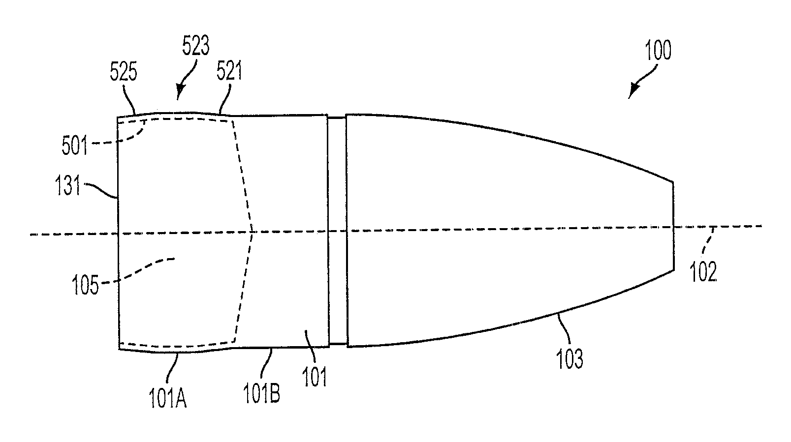
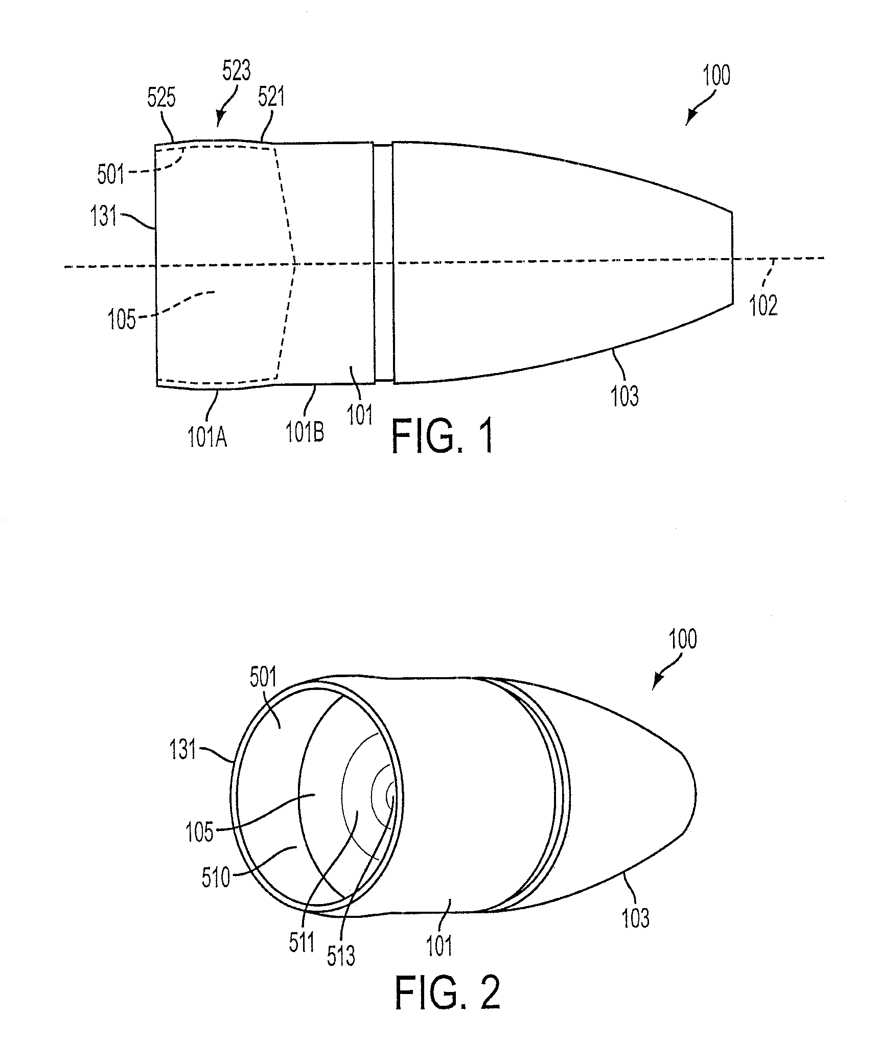
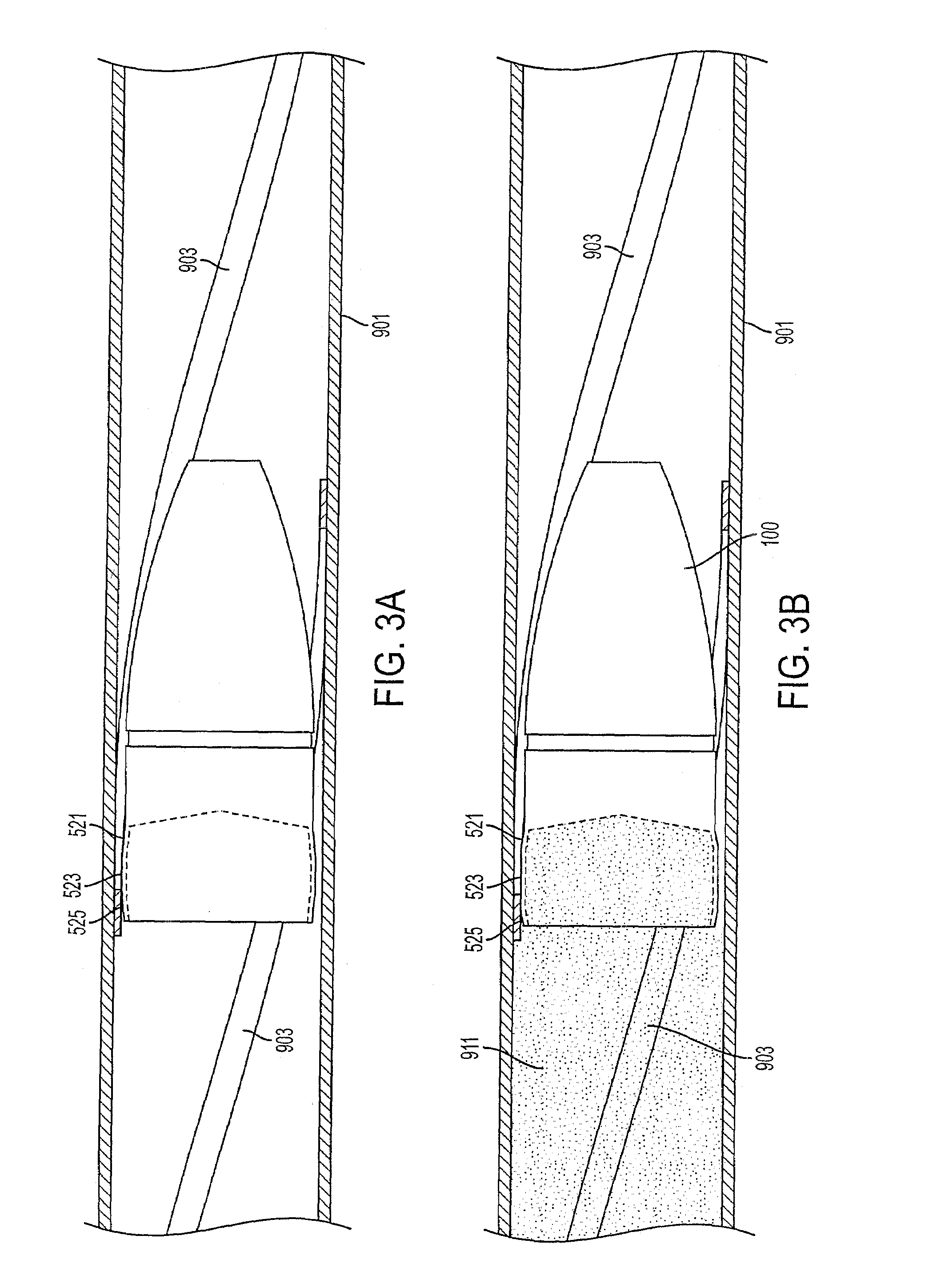
[0031]The embodiments of the invention discussed herein are generally designed to be used as a projectile discharged from a firearm. That is, they are bullets. The bullets are discussed in conjunction with a muzzleloading firearm because a muzzleloading firearm generally has a dual problem created because the bullet in a muzzleloader must pass into the barrel first backward as it is loaded, and then forward as it is fired. However, the bullet designs can be used in any type of firearm. During loading of a bullet, it is desirable to minimize contact between the bullet and the rifling to ease loading. Further, as some form of gas check is generally used for improved ballistic performance, it is also desirable to minimize barrel contact with the gas check to improve ease of loading and to inhibit residue formation in the barrel as the bullet and gas check are slid into the barrel. Once loaded, it is desirable to have the gas check and bullet form a sufficient seal with the barrel to se...


PUM


Abstract

Projectiles for firearms, specifically bullets, are discussed that include a rear thin-walled counter bore. The counter bore is designed to be a first size and shape when the bullet is loaded into the firearm and expand upon discharge of the firearm so as to force the walls of the counter bore into barrel rifling. The expansion may occur through the direct interaction of propellant gases with the counter bore walls, or at least partially indirectly though the inclusion of an expansion plug that is placed at least partially within the counter bore in a manner that the expansion plug can be driven further into the counter bore by the firing action of the firearm.

Description

CROSS REFERENCE TO RELATED APPLICATION(S)[0001]This application is a Divisional of and claims priority to U.S. patent application Ser. No. 11 / 234,613, filed Sep. 23, 2005 and currently pending, the entire disclosure of which is herein incorporated by reference.BACKGROUND OF THE INVENTION[0002](1) Field of the Invention[0003]The present invention relates to a firearm projectile or bullet, specifically a bullet for a firearm which provides for an expanding counter bore to provide decreased contact between the bullet and barrel during loading and with barrel rifling during firing.[0004](2) Background of the Invention[0005]Hunting and shooting with muzzleloaders is rapidly gaining popularity as a sport. The muzzleloader is essentially a primitive rifle, shotgun, or pistol, based on designs used during the early days of America and lacking the effective range of more modern center fire rifles and the speed of reloading available to cartridge firearms. Because of their popularity, many st...

Claims


Application Information

Patent Timeline
Patent Type & Authority Patents(United States)
IPC IPC(8): F42B30/00
CPCF42B14/00F42B14/02F42B30/003F42B30/02
Inventor OERTWIG, TERRANCE D.
Owner THOR INC
Learn More